A socket elbow changes pipeline direction—but under pressure, it also creates thrust that can separate unrestrained joints. That thrust needs an engineered load path.
For project managers overseeing ductile iron pipeline installation, deciding when to specify thrust blocks or restrained joints is critical to safety, scheduling, and cost control.
The right solution depends on design pressure, bend angle, soil conditions, available space, and the joint system—not simply the fitting size or socket configuration.
This guide explains how to assess those factors, distinguish sealing from mechanical restraint, and coordinate installation requirements with project specifications and manufacturer guidance before backfilling and testing.
When Does a Socket Elbow Need Thrust Protection?
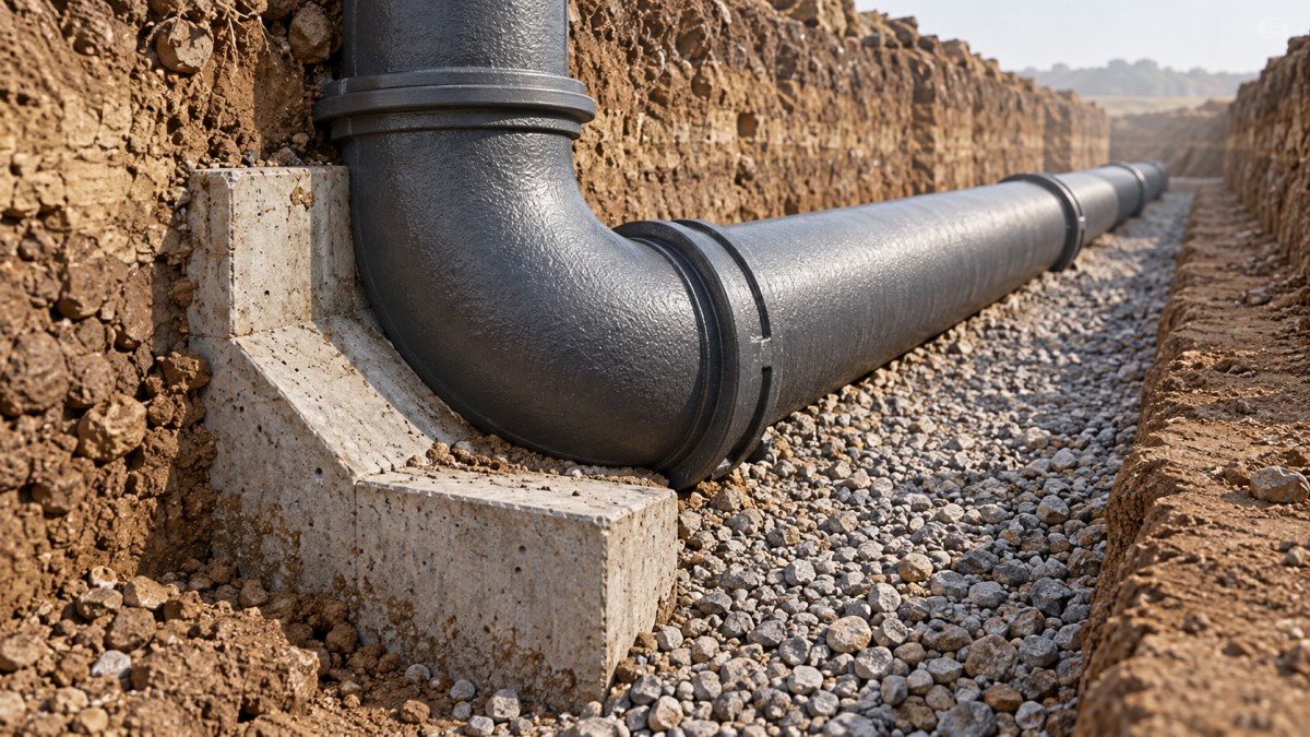
A pressurized elbow requires a verified way to transfer its resultant thrust into stable ground or another engineered structure. Unrestrained sockets cannot provide that resistance alone.
For conventional rubber gasket push-on joints, specify thrust blocks, an approved restraint system, or another engineered arrangement whenever the design identifies unbalanced thrust at the elbow.
A separate concrete block may be unnecessary when a properly designed restrained pipeline system already transfers the load. That decision requires documented calculations and approved details.
Do not interpret a small bend angle, shallow operating pressure, or tightly fitted socket as proof that restraint is unnecessary. Each changes demand, not the underlying requirement.
The practical question is therefore: where will the elbow’s pressure thrust go, and can every component along that load path safely carry its assigned load?
A Watertight Socket Is Not Necessarily a Restrained Joint
A standard elastomeric gasket seals the clearance between the socket and spigot. Its sealing function does not establish a rated capacity to resist axial separation.
Mechanical joints also require careful identification. A conventional gland and gasket arrangement should not be treated as restrained unless an approved restraint feature is included.
Restrained systems use specific mechanisms, such as locking segments, restrained glands, or other manufacturer-designed components. Compatibility depends on the exact pipe, fitting, size, and joint configuration.
During procurement, request the joint designation, allowable pressure, permitted angular deflection, installation instructions, and restraint limitations. A generic description such as “socket elbow” is insufficient.
Shanxi Datong Foundry Co., Ltd. manufactures ductile iron pipes, fittings, and rubber sealing rings. Confirm the proposed combination’s documented suitability before approving it for the project.
Which Pressure and Bend Details Determine the Load?
The designer should evaluate relevant operating, surge, and hydrostatic test conditions. The governing case is whichever produces the greatest demand relative to available system resistance.
For an equal-diameter elbow, a common pressure-thrust relationship is F = 2PA sin(θ/2), where P is pressure, A is internal area, and θ is bend angle.
This relationship represents the pressure component of resultant thrust. The design must also address applicable flow effects, external loads, elevation, and the actual pipeline arrangement.
As an illustration, a 90-degree elbow with a 300-millimeter internal diameter at 1 MPa develops approximately 100 kN of pressure thrust before applying design allowances.
Actual internal diameter matters in this calculation. Do not substitute nominal diameter without checking the pipe dimensions, and do not treat this example as a sizing recommendation.
Smaller angles reduce pressure thrust at otherwise identical conditions, but they do not eliminate it. Nearby tees, reducers, valves, and dead ends also require assessment.
When Is a Concrete Thrust Block the Practical Choice?
A thrust block can suit buried elbows where adequate excavation space and competent bearing soil are available. It transfers the elbow’s resultant load into surrounding ground.
Its effectiveness depends on geometry, bearing direction, soil capacity, concrete strength, and construction quality. A large concrete mass alone does not demonstrate adequate thrust resistance.
For straightforward bearing arrangements, designers relate thrust demand to allowable soil bearing resistance. Final dimensions must reflect the approved design basis and relevant safety provisions.
The block should bear against suitable undisturbed ground or specifically engineered support. Loose backfill, disturbed trench walls, and undocumented fill require additional assessment before construction.
Detail concrete placement to preserve joint access and any movement required by the design. Avoid enclosing gaskets, glands, or bolts unless the approved detail requires it.
Allow the concrete to reach the specified strength before applying the relevant pressure load. Link testing dates to verified strength requirements, rather than assumptions about elapsed time.
When Are Restrained Joints More Suitable?
Restrained joints often suit congested corridors, restricted excavations, and locations where a conventional block would conflict with adjacent utilities. They can also reduce concrete-related scheduling constraints.
However, restraining only the elbow’s sockets may leave the next unrestrained joint vulnerable. The required restraint commonly extends along adjacent pipe runs for a calculated distance.
That distance depends on pressure, diameter, cover, soil properties, groundwater, pipe characteristics, and layout. Use an accepted design method with the selected system’s published limitations.
Weak soils do not automatically make restrained joints adequate. Buried restrained pipelines still need sufficient soil interaction or another designed means of resisting the applied load.
Flanged connections can provide axial continuity, but forces still require a complete load path. Supports, anchors, fittings, and connected equipment must accommodate the transferred loads.
A Ductile Iron Double-Flanged Pipe may form part of a chamber assembly. Confirm flange compatibility, pressure rating, and support design wherever that assembly connects to the elbow.
What Should Project Managers Compare Before Approving Either Option?
Compare installed cost and construction risk together. A lower fitting price can be offset by larger excavations, imported concrete, curing requirements, utility conflicts, or rework.
For thrust blocks, review excavation access, verified bearing conditions, concrete placement, inspection access, and strength acceptance. These activities can directly affect the pressure-testing milestone date.
For restrained systems, review component availability, approved restraint lengths, installer familiarity, inspection requirements, and compatibility. Specialized components delivered late can disrupt an otherwise efficient installation sequence.
Consider future maintenance as well. Valve replacement, excavation beside an existing block, or changes to adjacent pipework can interrupt the load path established by the original design.
Combining blocks and restraints is sometimes appropriate, but their load sharing requires engineering justification. Do not assume both systems contribute equally or automatically provide independent protection.
What Must Be Checked Before Backfilling and Pressure Testing?
First, confirm that approved drawings identify the elbow, design conditions, thrust-control method, and any required restraint lengths. Resolve discrepancies before installation becomes hidden by backfill.
Next, verify the delivered joint components and installation records. Check gasket seating, insertion depth, permitted deflection, and any bolt-tightening or locking requirements specified by the manufacturer.
For concrete blocks, record bearing conditions, dimensions, placement, and required strength evidence. For restrained systems, verify every designated joint throughout the specified length, including connecting fittings.
Check test boundaries separately. Temporary caps, closed valves, and test assemblies may create additional thrust conditions that need approved restraint before the pipeline is pressurized.
Complete the specified backfill, support, air-release, and exclusion arrangements before testing. Pressure testing should verify an approved installation, rather than serve as evidence that missing restraint is acceptable.
Make the Decision Around a Verified Load Path
A socket elbow needs thrust protection whenever pressure produces an unbalanced force that its existing arrangement cannot safely resist. Sealing performance alone does not answer that question.
Choose thrust blocks where bearing conditions, space, and construction sequencing support them. Choose restrained systems where their calculated extent, component ratings, and ground interaction are suitable.
For project managers, the essential approval package is clear: design loads, verified site conditions, compatible components, installation details, and inspection hold points before backfilling and pressure testing.