K9 Ductile Iron Pipe Joint Types and Installation Requirements
K9 ductile iron pipe is usually selected where the pipeline must carry internal pressure while still tolerating ground movement, handling loads, and normal construction impact. The pipe wall class defines mechanical strength, but field performance often depends just as much on the joint. A well-chosen joint must seal under operating pressure, remain stable during laying, and allow the degree of angular deflection required by the route without overstressing the socket or the gasket.
Common joint types used with K9 ductile iron pipe
The most familiar arrangement is the push-in socket joint, sometimes called a Tyton-type joint in general trade usage. It uses a rubber gasket seated inside the bell, and the spigot end is inserted after lubrication. This joint is widely used in buried water lines because installation is relatively fast, the joint can accommodate limited angular deflection, and the seal becomes tighter when internal pressure acts on the gasket profile. However, that sealing behavior assumes the gasket is correctly seated, the insertion depth is reached, and the spigot surface is clean and free from coating lumps or impact damage.
Another type is the mechanical joint, where a gland compresses the gasket by means of bolts. This structure is useful where controlled assembly is preferred, where fittings need restrained tightening, or where disassembly may be required later. Mechanical joints are less forgiving of uneven bolt torque. If one side is tightened too early, the gasket can shift and create a leak path even when the final torque looks acceptable.
Flanged joints appear where the line connects to valves, meters, pumps, wall penetrations, or above-ground pipework. A flange creates a rigid connection and gives precise alignment, but it does not provide the same flexibility as a socketed buried joint. For that reason, flanged sections in buried service usually need careful thrust management and support. Excess settlement or misalignment can transfer bending stress directly to the flange faces and bolts.
Restrained joints are used when the pipeline must resist axial thrust without relying entirely on concrete thrust blocks. This often applies at bends, tees, reducers, steep slopes, casing entries, or unstable trench conditions. Different restrained systems exist, including locking segments, welded restraints where permitted by specification, and special socket designs. The installation detail matters more than the product name: if the restraint is rated for a certain deflection and pullout resistance, the field assembly has to match that exact condition.
How joint selection changes with site conditions
A straight run in stable soil may only require standard push-in joints with normal bedding and thrust blocks at fittings. That same pipe on a route with frequent changes in direction can become difficult to assemble if the available angular deflection is consumed at too many joints in sequence. In that case, the layout may need shorter pipe lengths, purpose-made fittings, or restrained sections to avoid forcing the socket.
Soil aggressiveness also matters. Where groundwater, chloride content, or stray current risk is present, the external coating and wrapping system should be reviewed together with the joint area. The socket and spigot zone is often where coating damage occurs during handling and insertion. A pipe body that meets specification can still become a maintenance problem if the joint coating is scraped away and left unrepaired before backfilling.
In pressure management zones, nearby appurtenances influence the joint decision. A control node using a Hydraulic Control Valve may introduce transient conditions depending on opening and closing behavior. When surge conditions are possible, joint restraint, anchor design, and deflection limits should be checked as one system rather than as separate components.
Installation points that affect sealing performance
The trench bottom needs to be shaped so the barrel is continuously supported while the socket area remains relieved. If the bell rests on hard ground, the installed line can develop point loading and angular stress before it is even pressurized. Bedding that looks level from above may still contain a localized stone under the barrel, and that single contact point can damage lining or alter alignment.
Before assembly, the socket interior and the spigot end should be wiped clean. Sand, loose coating flakes, timber splinters from packing, and small stones are frequent causes of immediate leakage. The gasket must sit evenly in its recess, without twist. A twisted gasket may allow insertion but can roll under compression and leave part of the sealing lip unloaded.
Lubricant should be compatible with the rubber compound and applied only where required. Too little lubricant can drag the gasket out of position. Too much applied blindly can trap debris or make it harder to see whether the gasket has shifted. Petroleum-based substitutes are sometimes used in the field when proper lubricant is missing; that can be a serious error if the elastomer is not resistant to it.
Insertion is not simply a matter of pushing until resistance increases. The spigot insertion mark is there for a reason. If the pipe stops short, the joint may still appear engaged but the gasket compression band will be wrong. If the insertion goes beyond the intended position in a forced assembly, available deflection may be reduced and the socket may be overstressed. With larger diameters, alignment tools or slings are usually needed so the spigot enters concentrically instead of shaving the gasket on one edge.
Angular deflection and thrust control
Every socket joint has a permitted deflection range, and that value should be treated as an installation limit, not as a target for every joint on the line. Deflecting the joint after full insertion is common practice, but the angle must remain within the stated tolerance for the diameter and joint design. Excessive deflection may not leak during the first hydrotest, yet it can shorten gasket life or increase the chance of pullout when pressure surges occur.
Changes in direction create axial thrust. At bends, tees, dead ends, and blank flanges, the pipeline needs a defined restraint method. Concrete thrust blocks are traditional, but they depend on soil bearing conditions and correct bearing area against undisturbed trench walls. In soft, wet, or recently backfilled ground, a thrust block that looks substantial can still move. Restrained joints reduce dependence on the block, though they do not remove the need to verify the full thrust path.
Handling, storage, and transport issues that show up later
Joint problems often begin before excavation. Pipes stacked on uneven timber can oval slightly at the socket if storage is poor. Lifting with unprotected chains may scar the spigot end. Gaskets exposed for long periods to sunlight, oil contamination, or mixed storage with incompatible materials can age before they are installed. None of these issues may be obvious once the line is in the trench, which is why incoming inspection should focus on socket roundness, cement lining edge condition, coating continuity, and gasket condition rather than only counting quantities.
During unloading, impact at the bell is especially damaging. A small chip or deformation at the socket mouth may not prevent assembly, but it can affect gasket seating or create a crack initiation point in coating and lining. Repairs should follow the relevant material procedure and should be completed before the pipe is lowered into the trench.
Frequent misjudgments in field installation
- Assuming any rubber ring that fits physically is acceptable, even when the profile or hardness does not match the joint design.
- Using insertion force as proof of correct assembly instead of confirming gasket placement and insertion depth.
- Taking the maximum joint deflection from a catalog and applying it on steep grade changes without considering cumulative alignment error.
- Backfilling one side heavily before the line is properly aligned, which can lock stress into the joint.
- Hydrotesting too early, before concrete supports or thrust blocks have developed the condition assumed in the design.
Where K9 ductile iron pipe is specified, the joint should be treated as part of the pressure system, the structural system, and the installation sequence at the same time. Most leakage problems are not caused by the pipe class itself, but by small deviations at the socket, gasket, alignment, or restraint stage that remain hidden until pressure testing or early service.
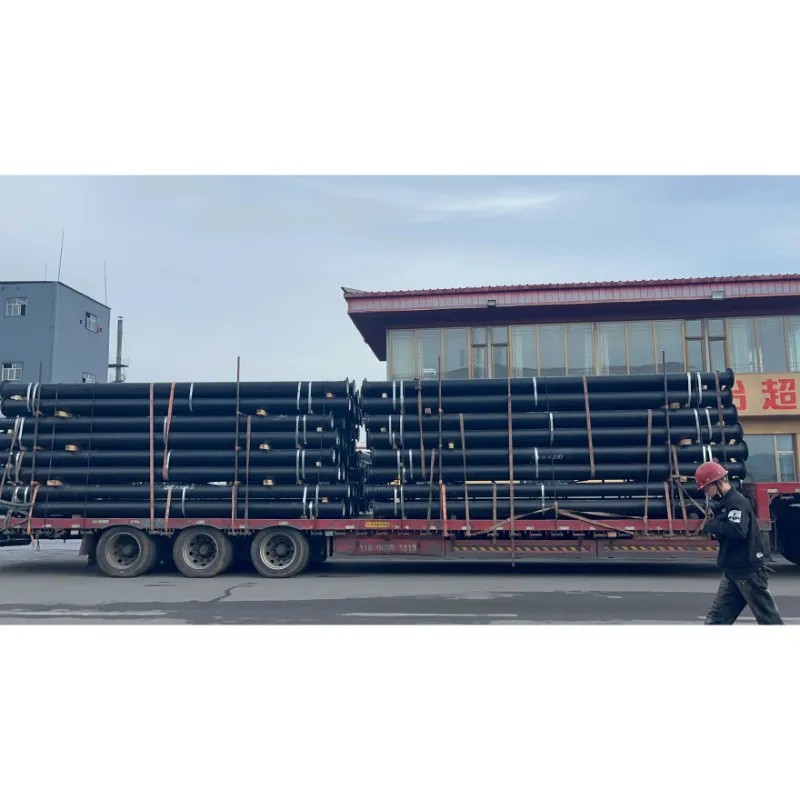
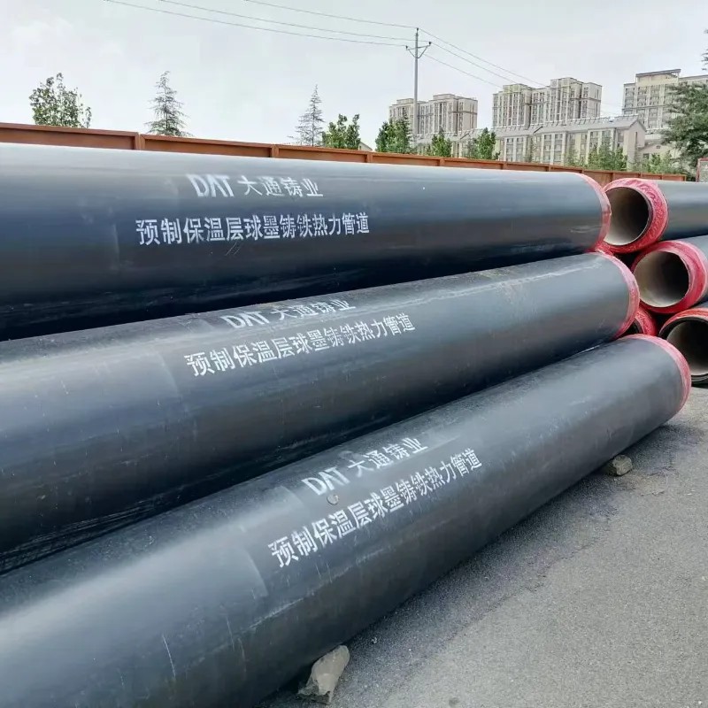
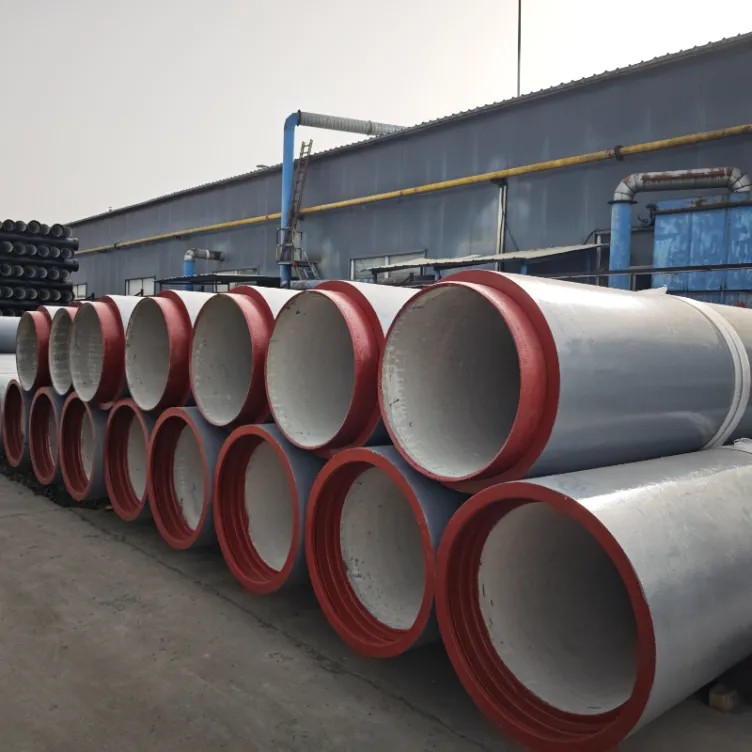
 Flanged Di PipeUsage: for Drinking Water/Sewage
Pressure: Pn10 / Pn16 / Pn25 / Pn40
Specification: DN80-DN2600mm
Origin: China
Production Capacity: 500000 Tons/Year Heating Pipe
 Jacking PipeK8 Ductile Iron Pipe is a widely used pressure pipe designed for water supply, wastewater transmission, and municipal infrastructure systems. Classified according to the K-series thickness standards, K8 ductile iron pipes offer enhanced wall thickness and superior pressure resistance compared to lower K grades, making them suitable for demanding operating conditions.
With proven durability, excellent mechanical strength, and long service life, K8 ductile iron pipes are a trusted choice for public utilities, contractors, and engineering projects worldwide.
Navigation
Send Us A Message

First class quality service and professional after-sales team.
Get in Touch
*We respect your confidentiality and all information are protected.