Preventing Turbulence and Erosion at Three-Way Fitting Connections
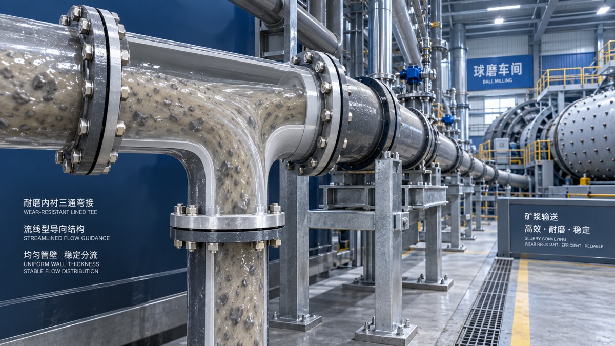
In a ball mill circuit, a three-way fitting is rarely just a simple branch. It is a point where slurry, process water, or flushing water changes direction, divides, or joins another stream. That change can disturb flow patterns immediately. When velocity is high or solids are abrasive, the result may be localized turbulence, pressure loss, thinning walls, vibration, and eventually a leak that forces an inconvenient shutdown.
Operators often notice the symptoms before they see the cause: a fitting that needs repeated patching, a branch line that loses flow stability, unusual noise at a junction, or wear concentrated on one side of the connection. Preventing these problems starts with treating the three-way fitting as a flow-control component, not merely a pipe connector.
Why three-way fitting connections wear faster
Fluid moving through a straight pipe develops a relatively predictable velocity profile. At a tee or wye connection, that profile is interrupted. Flow may strike the far wall, separate from the surface, circulate in a dead zone, or collide with another stream. In slurry service, each abrupt movement gives suspended particles more opportunity to hit the wall and remove material.
The greatest erosion is commonly found at the outer radius of a turn, the branch entrance, the opposite wall of a direct tee, and areas just downstream of a poorly aligned joint. A small installation error can turn into a large maintenance issue because abrasive slurry repeatedly follows the same damaging path.
Water-only lines can also suffer. While water is less abrasive, turbulence may create pressure fluctuations, cavitation risk under unfavorable conditions, and stress at joints or supports. The fitting’s geometry, internal finish, and operating conditions all matter.
Start with the flow path, not the catalogue description
The first practical question is how the line actually operates. Is the branch carrying a continuous slurry stream, an intermittent wash-down flow, or a low-volume instrument or drain connection? Does the main line feed the branch, or does the branch enter the main line? These arrangements produce different impact zones.
A standard 90-degree tee may be acceptable for clean water at moderate velocity, but it is often a harsh choice where dense slurry must make a sudden turn. A swept wye, lateral connection, or a branch with a larger turning radius can reduce the intensity of impingement. The goal is not to eliminate all turbulence—no branch connection can do that—but to avoid creating a concentrated particle strike zone.
When changing an existing layout, look beyond the fitting itself. A reducer immediately before a tee can accelerate flow into the junction. A valve placed too close downstream can create a second disturbance before the stream has recovered. Likewise, a short spool with an internal step or misaligned gasket can undo the benefit of a better fitting design.
Installation details that decide service life
Many premature failures are installation-related. Before tightening a three-way fitting connection, confirm that the incoming and outgoing pipe sections meet without forcing the fitting into position. Pipe strain can distort a joint, create uneven gasket compression, and place extra stress on the branch neck during pressure cycles.
- Check bore alignment: The internal diameters should meet as smoothly as possible. A protruding pipe end, displaced liner, or gasket edge becomes a target for abrasive flow.
- Support each leg: A branch must not carry the weight or vibration of an unsupported pipe run. Use suitable supports near the junction while allowing for thermal movement where applicable.
- Orient the branch deliberately: Avoid upward-facing dead legs where solids can settle unless the line is specifically designed for flushing. In slurry circuits, stagnant pockets are often the beginning of blockage and uneven wear.
- Use the correct tightening sequence: For flanged or mechanical joints, tighten evenly in a cross pattern and follow the relevant joint procedure. Uneven loading may cause leakage even when the components appear intact.
- Inspect internal transitions: An external joint can look correct while an internal offset remains hidden. Where access permits, inspect before commissioning.
It is tempting to solve a persistent leak by applying more torque. That can damage bolts, deform components, or crush sealing materials without addressing the real issue: pipe misalignment, poor support, a worn sealing surface, or pressure conditions beyond the joint design.
Match fitting material and lining to the medium
Material selection should reflect both the transported medium and the expected operating cycle. Clean water, wastewater, abrasive mineral slurry, and chemically treated process water do not place the same demands on a fitting. Ductile iron offers strong mechanical performance for many water, fire protection, wastewater, and industrial pipeline duties, particularly where external loads and pressure resistance matter. For abrasive slurry sections, however, operators should evaluate whether additional wear protection, a suitable internal lining, or a purpose-designed wear component is required.
Coatings and linings deserve the same attention as the base metal. Cement mortar linings are widely used for water applications, while epoxy systems may suit specified corrosion environments. In a ball mill area, the question is more specific: will the lining resist the actual particle size, solids concentration, temperature, pH, and flow velocity? A coating selected only for corrosion resistance may not be the right answer for severe sliding abrasion.
For utility water and supporting process lines around a mill, properly selected ductile iron pipe can provide a durable foundation. Shanxi Datong Foundry Co., Ltd. manufactures ductile iron pipes, fittings, and rubber sealing rings through integrated smelting and casting processes. Its Ductile Iron Pipe Export ISO2531 & EN545 range covers nominal sizes from 80 mm to 2600 mm and is intended for applications including municipal water supply, fire protection, wastewater, and industrial pipelines. The available protective options, such as metallic zinc with bituminous coating, cement mortar lining, or epoxy coating, should be selected according to the service environment rather than by appearance alone.
Control velocity before it controls the fitting
Velocity is one of the strongest drivers of erosion. As speed rises, particle impact energy rises quickly, especially where the stream turns sharply. The correct operating velocity depends on slurry characteristics and the process objective, so it should be established by the plant’s process and piping design requirements. What operators can do is watch for conditions that push flow beyond its intended range: partially closed valves, unexpected pump changes, blocked parallel lines, or an altered slurry density.
A sudden increase in differential pressure across a branch arrangement may indicate restriction, buildup, or a developing internal failure. Do not assume the pump is the only source of the problem. A worn three-way fitting can change the flow split, and an accumulating deposit can redirect the stream toward a vulnerable wall.
A field inspection routine that catches wear early
Inspection is most useful when it is targeted. During planned stops, examine the known high-impact zones rather than looking only for obvious external leakage. Check for wall thinning, coating loss, rust staining around joints, distorted flanges, loose supports, and vibration marks where pipework contacts steelwork.
Where the system allows it, compare wall thickness readings at the branch inlet, outer turn, and downstream run with readings from a nearby straight section. The pattern tells a story. Uniform loss may point to general abrasion or corrosion; sharply localized loss usually points to turbulence, misalignment, or direct impingement. Record these observations with operating conditions such as pump speed, density, and hours since the previous inspection. Over several maintenance cycles, this record becomes much more useful than replacing fittings only after failure.
Common fixes that can make the problem worse
Adding a smaller branch to “increase pressure” is a common misunderstanding. Restricting the branch may increase local velocity and worsen erosion. Another weak fix is placing a hard patch over a worn external area while leaving the internal flow obstruction unchanged. The patch may temporarily hold pressure, but the abrasive stream continues to attack the same location.
Replacing a failed tee with an identical component without reviewing alignment and flow direction also repeats the original problem. If one side of every replacement wears first, the fitting is giving clear evidence that the piping arrangement needs attention.
Keep the connection stable over time
A reliable three-way fitting connection comes from several modest decisions working together: a geometry suited to the flow direction, a material and lining matched to the medium, smooth internal alignment, adequate support, and regular inspection of predictable wear zones. None of these measures is dramatic on its own. Together, they reduce the chance that a small disturbed-flow area becomes the source of slurry loss, pressure instability, or an unplanned mill interruption.
For operators, the practical standard is simple: the branch should carry its intended flow without visible leakage, abnormal vibration, accumulating solids, or recurring wear in the same location. When any of those signs appears, investigate the flow path early. A timely correction at one three-way fitting is usually far easier than managing a failed connection in the middle of production.
Navigation
Send Us A Message

First class quality service and professional after-sales team.
Get in Touch
*We respect your confidentiality and all information are protected.