Pressure Testing Ball Valves Before Commissioning: Key Quality Checks
A ball valve that appears sound during installation can still fail at commissioning because pressure testing exposes conditions that normal handling does not: casting discontinuities, damaged seat rings, incorrect assembly, flange misalignment, stem leakage, or a test arrangement that loads the valve in an unintended way. The essential control is not merely reaching a specified pressure. It is demonstrating that the valve body, pressure boundary, closure mechanism, and installed connections perform as required by the governing valve standard and the piping-system test procedure.
Acceptance criteria must be established before the test begins. API 598 and ISO 5208 are commonly referenced for valve inspection and pressure testing, while ASME B16.34 may govern pressure-temperature design requirements for many steel valves. The applicable project specification, piping code, valve data sheet, and manufacturer’s instructions determine the actual test medium, pressure, hold period, permitted leakage rate, and test sequence. These documents should be reconciled rather than treated as interchangeable: a shell-test requirement is not the same as a seat-leakage requirement, and a factory acceptance test does not automatically validate an installed valve and its field joints.
Separate pressure-boundary integrity from shut-off performance
A commissioning test should distinguish between two different functions. The shell or body test verifies the integrity of the pressure-retaining envelope: body casting or forging, end connections, bonnet or stem sealing areas, and assembled joints. The seat test verifies whether the closed ball valve can isolate pressure across its seats. Combining these functions into one undocumented test often makes the failure source unclear.
For a shell test, the valve is generally placed in the position required by the approved procedure, filled completely when water is used, and pressurized in a controlled manner. Inspectors should examine the body surface, flange necks, threaded or welded ends, stem packing area, body joints, drain or vent plugs, and any cavity-relief fittings. Visible sweating, droplets, pressure decay not attributable to temperature stabilization, or deformation requires investigation. Applying sealant to conceal a defect is not a corrective action; the cause must be identified, documented, and assessed against the relevant acceptance standard.
Seat testing requires the valve to be fully closed and pressure to be applied to the specified side of the closure. A conventional floating-ball valve may have a preferred pressure direction for optimal seat loading, whereas trunnion-mounted and double-block-and-bleed designs have different internal sealing arrangements. Bidirectional capability should never be assumed from the external appearance of a ball valve. The valve marking, data sheet, and installation arrow, where provided, should control the test direction.
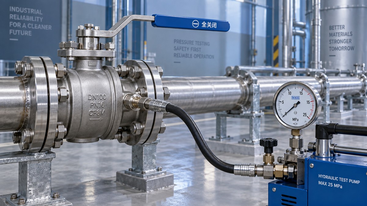
Test configuration can create false failures—or hide real ones
Many apparent valve failures originate in the test setup. Blind flanges, temporary spools, test headers, hoses, gauges, and isolation devices must all be rated for the planned test pressure. A leaking temporary connection can be mistaken for seat leakage; conversely, a second isolation valve left closed can prevent pressure from reaching the valve under examination.
The valve’s position also matters. A ball valve should not be left partly open unless the procedure specifically requires it. In a partially open position, high-velocity filling or draining can damage soft seats, and pressure trapped in the body cavity may produce misleading observations. During hydrostatic testing, air must be vented from the valve and test section. Entrapped air reduces test reliability and stores significantly more energy than water if a component fails.
Pneumatic testing requires much tighter controls because compressed gas releases stored energy rapidly. It should be used only where a hydrostatic test is impracticable or prohibited by the system service, materials, cleanliness requirements, or freeze risk, and only under an approved procedure. Exclusion zones, incremental pressurization, calibrated instrumentation, restrained temporary equipment, and a documented emergency plan are central controls—not administrative formality.
Check the valve before pressurizing it
Pressure testing cannot compensate for incomplete incoming or installation inspection. The valve identity should match the line list and piping isometric: nominal size, pressure class or PN rating, body and trim materials, end connection, bore type, actuation method, and service designation. A reduced-bore valve may be technically acceptable for isolation, but it can affect pigging, flushing, flow capacity, and pressure-drop calculations. These are design questions that should be resolved before the test, not after the line enters service.
Inspect the ball, seats, and bore where accessible. Construction debris, welding slag, paint overspray, sand, packing material, or damaged protective caps can score a soft seat during the first operation. The valve should be cycled through its full travel before testing, with torque and travel observed for abnormal resistance. Manual levers must be secure and correctly indexed. Gear operators and actuators require verification of open and closed stops, local position indication, fail position where applicable, and any interlocks or permissives associated with the system.
Stem sealing deserves particular attention. A valve may pass a closed-seat test yet leak through packing during cycling or after pressure stabilization. Check packing-gland adjustment against manufacturer instructions; excessive tightening can increase operating torque and shorten packing life, while insufficient loading may allow leakage at the stem. For valves fitted with emissions-control packing or special fire-safe construction, the relevant certification and assembly requirements should remain traceable in the quality record.
Installed flange joints need their own inspection logic
In ductile iron pipe systems, the ball valve is frequently connected through flanged adaptors, restrained joints, or flanged fittings rather than directly welded into a steel line. This makes interface control as important as valve inspection. Confirm flange-face compatibility, gasket type and dimensions, bolt grade, bolt length, washer use where specified, and tightening sequence. Uneven bolt loading or a gasket selected for the wrong face profile can produce leakage that is incorrectly attributed to the valve body.
Pipe alignment should be checked before final bolting. A valve must not be used to pull misaligned pipe ends into position. Ductile iron pipe, fittings, and valves have different geometry, mass, and support needs; external bending loads transferred through a flanged ball valve can distort the joint or impair operating torque. Adequate supports should be installed before testing, especially around heavy actuated valves and valve chambers where unsupported pipe movement can load the assembly.
Pressure testing also does not prove resistance to every operating transient. Water hammer, pump start-stop cycles, rapid valve closure, and air release behavior can create short-duration pressure conditions different from a static test. Where the duty involves frequent cycling or surge exposure, verify that the valve’s pressure rating, seat material, actuator closing time, and system surge analysis are compatible with the intended operation.
Instrument control and test records determine whether the result is defensible
A test result is meaningful only if the pressure reading is credible. Gauges or transmitters should have current calibration status, an appropriate measuring range, and sufficient resolution to identify meaningful pressure change. A gauge with an excessively high full-scale range can obscure a small but relevant loss; one operated near its limit is vulnerable to damage and poor accuracy. At least one readable indication should be available at the test point, and the procedure may require additional instruments at remote or elevated sections to account for hydrostatic head.
Before declaring a pressure loss, allow for stabilization. Water temperature changes, elastic expansion of hoses, gasket seating, and removal of residual air can change the reading without indicating a leak. The inspection record should capture the valve tag, manufacturer and model where available, size and rating, test medium, test pressure, start and finish times, ambient conditions if relevant, instrument identifiers, valve position, applied test direction, observed leakage, and disposition.
Where a ball valve is part of an automated pressure-control arrangement, the test boundary must be defined carefully. An adjacent Hydraulic Control Valve, relief valve, bypass, or pilot circuit can alter pressure distribution or unintentionally bypass the isolation valve being assessed. Temporary isolation should preserve safety protection where required and should be removed only under controlled reinstatement procedures.
Common acceptance errors
- Treating no visible external leak as a complete pass. A valve can be externally dry while passing unacceptable leakage across closed seats.
- Testing only one flow direction. This can miss a directional seat issue or an incorrect installation orientation.
- Using system test pressure without confirming valve limits. The applicable pressure-temperature rating and approved test basis must be checked for the installed valve and its weakest connected component.
- Leaving air in a hydrostatic test section. The result becomes less reliable and the stored-energy hazard increases.
- Skipping post-test functional checks. A valve can seal during the test but bind after pressure release, particularly where packing adjustment, flange stress, or actuator stops are incorrect.
After depressurization, drain and vent the test section safely, inspect again for delayed leakage, and cycle the ball valve to confirm smooth operation. Any water-sensitive cavity, actuator enclosure, or instrument connection should be restored to its service condition. The commissioning release should depend on traceable evidence that the specified shell, seat, operational, and installation checks have passed—not on a single pressure reading or an informal visual inspection.
Navigation
Send Us A Message

First class quality service and professional after-sales team.
Get in Touch
*We respect your confidentiality and all information are protected.