Inspection Points for Three-Way Fittings in Pressurized Pipe Networks
Inspection Points for Three-Way Fittings in Pressurized Pipe Networks
In pressurized pipe networks, every three-way fitting must withstand internal pressure, maintain reliable sealing, and preserve flow stability at branch connections. For quality control and safety managers, systematic inspection of dimensions, casting integrity, coating quality, joint surfaces, and pressure performance is essential to prevent leakage, rupture, and costly downtime. This guide outlines the critical inspection points for ductile iron three-way fittings before installation and service.
A branch connection is rarely a minor detail. It changes the load path through the pipework, introduces a local disturbance to flow, and often becomes a high-consequence point during pressure testing or later maintenance. A three-way fitting may be a tee, reducing tee, or another branch configuration, but the inspection logic is similar: verify that the component supplied is the component designed, then confirm that its material condition and joint interfaces are fit for the operating duty.
Start with Traceability and Design Compatibility
Inspection should begin before visual examination. Check the purchase specification, approved drawings, packing list, and casting identification against the actual fitting. The nominal diameter of the run and branch, pressure class or design pressure, end connection type, lining requirement, coating system, and applicable project standard should all be clear. A fitting can appear sound yet be unsuitable if the branch size, socket arrangement, flange drilling, or allowable pressure differs from the approved design.
Standards such as ISO 2531, EN 545, EN 598, or relevant AWWA fitting standards may be referenced by a project, but their applicability depends on service conditions and contractual requirements. Inspectors should not assume that a standard designation alone settles every issue. Pressure duty, medium, external environment, restraint arrangement, and required coating performance still need to be checked against project documents.
Traceability is particularly useful when a nonconformance appears later. Markings should remain legible enough to link the fitting to its batch, heat, production record, or inspection documentation as required by the order. If repainting or site handling obscures identifiers, record them before installation.
Dimensional Checks: More Than Nominal Size
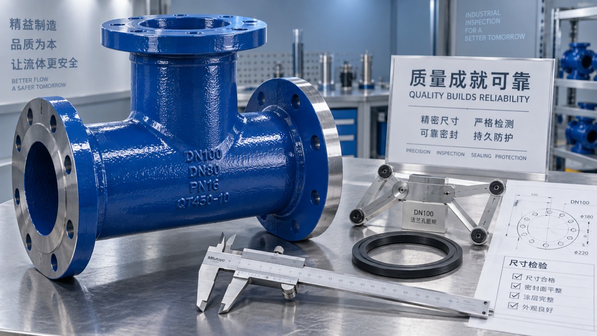
A ductile iron three-way fitting must mate correctly with the connecting pipes, glands, gaskets, flanges, or couplings. Measure the major dimensions using calibrated tools appropriate to the tolerance being verified. Important points include socket depth, spigot insertion length where applicable, outside diameter at the joint area, flange outside diameter, bolt-hole pattern, face condition, branch angle, and overall center-to-end dimensions.
Branch angle deserves attention because a small angular error can create assembly stress in a rigid pipeline layout. Likewise, a reducing tee must be reviewed as a complete geometry, not simply as one main diameter and one smaller branch diameter. Incorrect centerline dimensions may force field crews to pull pipe into position. That practice can preload joints and make leakage during commissioning more likely.
For flanged ends, inspect bolt holes for number, diameter, spacing, and alignment. For socketed ends, inspect the gasket seat, retaining groove where present, and internal profile. A visual check alone may miss an uneven socket or an imperfection that prevents a rubber sealing ring from seating uniformly.
Casting Integrity and Surface Condition
Ductile iron provides useful strength and toughness for pressurized water and utility networks, but casting quality remains central to reliability. Inspect the body, hub transitions, branch intersection, and flange necks under adequate lighting. Look for cracks, laps, folds, cold shuts, visible porosity, sand inclusions, sharp fins, excessive grinding, and areas with unusual surface texture.
The junction between the run and the branch is especially important. It is where geometry changes abruptly and where pressure loading, installation loads, and possible ground movement can combine. A local repair or heavy grinding in this zone should be assessed against the applicable acceptance criteria rather than accepted casually. The issue is not cosmetic appearance; it is whether wall continuity and required section thickness have been preserved.
Where the project calls for supplementary examination, such as dimensional scanning, ultrasonic thickness checking, magnetic particle examination, or documented pressure testing, use the specified method and acceptance criteria. Do not substitute an informal visual judgment for a required test. Conversely, avoid imposing extra tests without considering whether the method is technically relevant to the fitting design and contract requirements.
Inspect Coatings, Linings, and Joint Surfaces Separately
External coating and internal lining protect different sides of the fitting and should be evaluated independently. The external surface may face buried soil, moisture, mechanical handling, or atmospheric exposure. The internal surface may face potable water, raw water, wastewater, or another medium with its own corrosion and hygiene requirements. Confirm that the specified system is present and that its condition has not been compromised during storage or transport.
Look for bare metal, blistering, flaking, pinholes, impact damage, poor edge coverage, contamination, and incomplete touch-up. Coating thickness measurements may be necessary where required by the specification, but readings should be taken using a suitable calibrated gauge and interpreted according to the relevant coating system. A single thickness value does not prove overall quality if adhesion, coverage, or surface preparation is poor.
Joint surfaces require a stricter standard of cleanliness. Socket interiors, gasket contact areas, flange faces, and bolt holes should be free of loose coating, grit, rust scale, and damage that could interfere with sealing. Repair coating should not build up on a gasket seat or flange face. That seemingly small defect can lead to uneven compression and a leak that appears only after the line is pressurized.
Pressure Capability and Test Readiness
A pressure test is a system event, not merely a fitting event. Before hydrostatic testing, confirm that the installed three-way fitting has appropriate thrust restraint or anchorage where the design requires it. Changes in direction and branch connections generate hydraulic thrust. A fitting that passes a factory test can still move or separate in the field if joint restraint, concrete thrust blocks, restrained joints, or surrounding support conditions are inadequate.
During pre-test inspection, verify gasket placement, bolt tightening sequence for flanged joints, branch isolation arrangements, venting points, and support of connected pipework. Air pockets can distort test results and introduce avoidable hazards. The test pressure, duration, allowable leakage method, and safety exclusion zone should follow the project procedure and applicable local requirements; they should not be selected from a generic rule of thumb.
If leakage occurs, record its location before dismantling. Distinguish between leakage at a gasket interface, a damaged flange face, loose or uneven bolting, coating debris in a socket, and a possible defect in the fitting body. Treating all leaks as “gasket problems” can conceal the actual cause and repeat the failure at the next branch connection.
Fit the Inspection to the Entire Connection
A three-way fitting should not be inspected in isolation from the adjacent components. Transitional items often determine whether the assembly can absorb tolerance variation and remain serviceable. For repair work or connections between compatible socketed sections, a Double-Socket Sleeve may be considered within the broader fitting arrangement, provided its dimensions, pressure rating, joint type, and restraint requirements are verified for the specific line.
Manufacturing control also matters before the fitting reaches site. Shanxi Datong Foundry Co.,Ltd., located in Chuandi Industrial Park, Zezhou County, integrates smelting and casting processes for ductile iron pipes, fittings, and rubber sealing rings. For buyers and project teams, an integrated production route can make coordination of material, fitting geometry, and sealing components more direct, but incoming inspection should still be based on the approved specification rather than assumptions about origin.
The most useful inspection record is practical: identify the fitting, note its location or intended installation point, document measurements and visible findings, retain relevant certificates or test records, and photograph any nonconformance before correction. This creates a defensible handover trail and gives maintenance teams meaningful information if the branch connection is revisited years later.
For safety-critical networks, release a fitting for installation only after design compatibility, casting condition, joint integrity, protective systems, and test preparation have all been reviewed together. The branch is where several small deviations can meet. Catching them before backfilling or commissioning is usually far simpler than diagnosing a leak beneath an operating pipeline.
Navigation
Send Us A Message

First class quality service and professional after-sales team.
Get in Touch
*We respect your confidentiality and all information are protected.