Designing Flow Distribution with Three-Way Fittings in Water Pipelines
A three-way fitting is not merely a point where one pipe becomes two. In a water pipeline, it creates a hydraulic decision point: how much flow enters a branch, how much head is lost at the junction, how transient pressures are transmitted, and whether the connection can be installed and maintained without weakening the main line. A tee that is geometrically correct but poorly matched to duty conditions can leave a branch under-supplied, impose avoidable pumping cost, or complicate isolation during repairs.
For municipal transmission, distribution networks, industrial water systems, and large utility connections, the fitting should therefore be selected as part of the branch arrangement rather than as an isolated catalog item. The main diameter, branch diameter, flow direction, operating pressure, valve layout, restraint method, and construction sequence all affect the result.
Start with the hydraulic role of the branch
The first question is whether the branch is intended to take a regular operating flow, provide intermittent supply, feed a future extension, serve a fire-water connection, or function as a bypass or drain. These duties create different design priorities.
A continuous service branch must receive adequate pressure under both normal and peak demand. Its diameter should be based on the required branch flow and acceptable velocity, not simply on the nearest standard outlet size. Reducing a branch too aggressively may lower initial fitting cost, but it increases local velocity and friction loss. It can also make pressure recovery difficult when the downstream network is extended.
An infrequently used branch presents a different concern. Low turnover can create water-quality and sediment-management issues in dead-end or lightly circulated lines. Where a branch is retained for future use, the design should provide a positive means of isolation and a practical arrangement for flushing or commissioning. The tee itself does not solve these operational issues; it establishes the geometry that either enables or restricts later control.
Flow direction matters as much as nominal diameter. In a conventional equal or reducing tee, flow diverted through a 90-degree outlet changes direction abruptly. The resulting turbulence and local head loss are inherent to the connection. Where a branch needs a substantial share of the main-line flow, or where energy consumption is sensitive, engineers may need to assess whether a swept connection, a differently oriented branch, or a revised network layout provides a better hydraulic outcome. A three-way fitting should not be treated as hydraulically neutral.
Size the fitting around the governing operating condition
Branch sizing is often checked against an average demand figure, while the system is actually governed by a higher-demand condition, a fire-flow scenario, pump duty, or a staged operating arrangement. The relevant check is the pressure available at the branch downstream of all realistic losses: pipeline friction, fittings, valves, meters, elevation change, and any pressure-control devices.
For a reducing tee, the main barrel should preserve the required transmission capacity through the run. The branch outlet should be sized to the design flow of the take-off. This sounds straightforward, but two recurrent mistakes deserve attention:
- Assuming the branch can receive its required flow because its nominal diameter appears adequate, without verifying residual pressure at the point of connection.
- Selecting an equal tee where the branch is materially smaller, then relying on a reducer immediately downstream. This can add joints, occupy more installation space, and introduce another potential interface for leakage or restraint complications.
A factory-manufactured reducing tee often gives a cleaner arrangement when the branch size is known. It reduces the number of components and makes the bill of materials easier to control. However, a separate reducer may be justified when the downstream diameter is uncertain, when phased construction is planned, or when the branch needs to remain temporarily capped at a larger future connection size.
The pressure class of the fitting also needs to follow the system’s actual pressure envelope, not only its normal static pressure. Pump start-stop events, valve closure, sudden changes in demand, and air movement can generate transient pressures. The tee is part of the pressure boundary, and the branch connection can become a location where pressure-wave behavior changes because of the discontinuity in pipe geometry. Surge analysis may be warranted for long pumping mains, high-head systems, rapidly operated valves, and large-diameter branches.
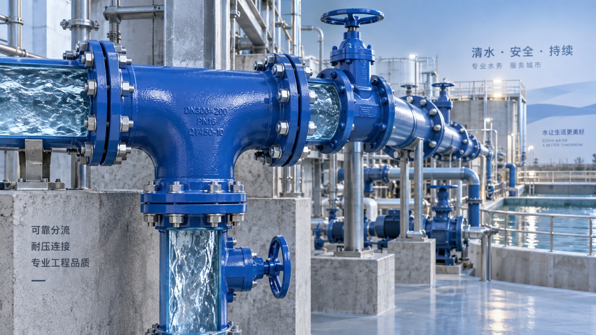
Connection type determines much of the installation risk
In ductile iron water systems, flange, socket-and-spigot, mechanical-joint, and restrained joint arrangements each impose different field requirements. The most suitable choice depends on whether the pipeline is buried or exposed, whether axial thrust is significant, how much alignment tolerance is needed, and whether later dismantling is expected.
Flanged tees are useful in chambers, plant rooms, meter stations, and valve assemblies where access is available and components may need to be removed. Their limitations are equally important: flanged joints require disciplined bolt tightening, suitable gasket selection, adequate support, and sufficient room around the assembly. They are rarely an excuse to transfer an above-ground arrangement directly into a congested buried trench.
Socket or push-on joint fittings can simplify buried installation, but they do not automatically provide restraint against thrust. At a tee, the change in flow direction and branch pressure create unbalanced forces. The project design must establish how those forces are resisted—through restrained joints, designed thrust blocks, or another approved restraint system. The decision cannot be deferred to the installer after excavation begins, because soil condition, trench dimensions, joint configuration, and access affect the feasibility of the selected method.
Mechanical joints provide useful adjustment during tie-ins and constrained installations, particularly where minor alignment correction is required. Their performance still depends on correct gland positioning, bolt tightening, gasket seating, and the restraint design where applicable. A fitting schedule that identifies only diameter and pressure rating is incomplete if it does not specify the end configuration and restraint requirement.
Do not separate the tee from valve and access planning
A branch connection needs an operating philosophy. If the branch must be isolated without interrupting the main, the isolation valve belongs close to the tee, with enough clearance for operation and repair. If the main line may also need sectional isolation, valve locations should be coordinated so that a branch failure does not force an unnecessarily large shutdown area.
Valve selection depends on duty. A gate or butterfly valve may be used for isolation in many water applications, while a control device may be needed where branch pressure or flow must be managed. In installations involving process water or media where shutoff behavior and material compatibility require closer review, a Diaphragm Valve may be considered within the wider valve arrangement. It should not be assumed to be a substitute for the pipeline isolation function without checking pressure rating, flow capacity, maintenance access, and the operating medium.
Branch valves, air valves, meters, drains, and sampling points can turn a simple tee installation into a compact assembly with difficult access. Drawing clearances should account for wrench movement, cover removal, actuator travel, lifting space, chamber entry, and future replacement—not only the footprint of the pipe and fitting. A branch that can be installed but cannot be isolated or serviced safely is not a complete solution.
Material and coating choices must match the exposure, not just the conveyed water
Ductile iron three-way fittings are valued in water pipelines for strength, dimensional stability, and compatibility with ductile iron pipe systems. Their long-term performance, however, depends on the complete corrosion-protection approach. Internal lining should suit the water quality and service conditions; external coating and, where needed, supplementary protection should reflect soil aggressiveness, groundwater conditions, installation environment, and project specifications.
The fitting body, joint components, bolts, glands, gaskets, and restraints should be reviewed as an assembly. It is not sufficient for the main fitting to meet the required material specification if exposed fasteners or incompatible ancillary components become the limiting items. For projects supplied across markets, documentation should identify the applicable product standard, dimensional series, pressure designation, lining and coating system, and test requirements. Equivalent-looking fittings are not necessarily interchangeable when flange drilling, socket dimensions, pressure classes, or certification requirements differ.
Protect the connection during construction
Many branch-connection defects originate in the installation process rather than in the casting. Bedding must support the fitting and adjacent pipes without point loading. The branch should not be pulled into alignment by forcing the joint, and the trench should provide enough working room to assemble joints correctly. Heavy fittings require an approved lifting method that avoids damage to linings, coatings, socket faces, and gasket seats.
Before backfilling, verify orientation, branch elevation, joint insertion or bolt tightening, restraint installation, valve direction, and accessibility of caps or temporary closures. Pressure testing should follow the applicable project procedure and account for the test section’s air removal and safe restraint. If a new branch is connected to an existing system, the tie-in plan should address shutdown duration, dewatering, disinfection where required, contamination control, and restoration of service.
The best three-way fitting arrangement is the one that distributes the required flow while preserving the integrity and operability of the main. That outcome comes from aligning hydraulic duty, fitting geometry, pressure and restraint design, joint type, valve arrangement, corrosion protection, and field installation conditions before material is released for procurement. Treating the tee as a simple commodity usually shifts unresolved engineering decisions to the site, where they are slower and more expensive to correct.
Navigation
Send Us A Message

First class quality service and professional after-sales team.
Get in Touch
*We respect your confidentiality and all information are protected.