How Ductile Iron Pipe Supports Reliable Municipal Water Distribution
Reliable Distribution Starts with the Pipe System, Not the Pump Station
Municipal water networks remain reliable when the pipeline can tolerate pressure changes, ground movement, installation variation, and decades of buried service without losing joint integrity. Ductile iron pipe is widely selected for these conditions because its material behavior combines high load resistance with useful ductility. The result is a pressure pipe system suited to transmission mains, distribution lines, pump station connections, and rehabilitation work where service interruption is difficult to accept.
For a municipal network, pipe performance cannot be judged by wall strength alone. A line can use a strong pipe body yet still experience leakage or operational issues if joints, bedding, thrust restraint, corrosion protection, and access structures are treated as separate decisions. Ductile Iron Pipe for Municipal Water Projects works best when these elements are specified as one connected system.
Pressure Resilience During Normal and Abnormal Operation
Water pressure is rarely constant across a municipal network. Elevation changes, pump cycling, valve operation, demand shifts, and emergency shutdowns create pressure conditions that differ from the nominal design value. Ductile iron has a graphite structure that gives the material greater toughness than traditional brittle cast iron. This allows the pipe to resist internal pressure while retaining a degree of deformation capacity under external loading or localized ground stress.
Pressure class selection should therefore start with the actual hydraulic envelope rather than a single operating-pressure figure. Static pressure at the lowest point of a route can be substantially higher than pressure near a reservoir or elevated zone. Transient pressure also requires separate attention. A rapid valve closure or sudden pump stop can create a surge that is short in duration but severe enough to challenge joints, fittings, restraints, and appurtenant connections.
Increasing pipe wall thickness is not a substitute for reviewing surge conditions. A pipe barrel, gasketed joint, and restrained fitting assembly respond differently to transient forces. The design should identify where force changes direction, where isolation valves divide a pressure zone, and where air may enter or leave the line. These locations often determine whether a system remains stable during an upset event.
Joint Performance Controls Leakage More Than Pipe Appearance
A ductile iron pipe system typically relies on push-on or mechanical joint arrangements with elastomeric sealing rings. The pipe spigot, socket geometry, gasket profile, lubrication practice, insertion depth, and cleanliness of the joint all affect sealing performance. A joint that looks seated from the outside may still be compromised by a rolled gasket, damaged coating at the spigot end, grit in the socket, or incomplete insertion.
Leakage risk rises when crews treat every joint as identical. Curved routes, grade transitions, cut pipe lengths, restrained sections, and connections near chambers require more deliberate layout control. Pipe ends should be aligned before jointing rather than pulled into position by excessive force. Misalignment transfers load to the gasket and may reduce the joint's ability to accommodate later settlement.
Field marks on the spigot are useful only when they correspond to the specific joint design and remain visible during installation. They indicate insertion depth, but they do not confirm gasket position by themselves. Inspection should include the cleaned socket, correct gasket seating, approved lubricant, aligned insertion, and a visual confirmation around the joint after assembly. This sequence prevents many defects that are expensive to locate once the trench is backfilled.
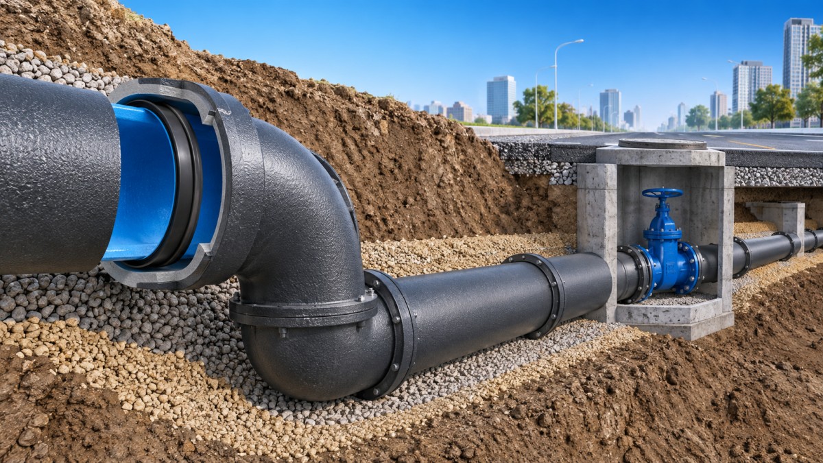
Buried Loads Need a Route-Specific Response
Ductile iron pipe performs well beneath roads and developed areas because it can carry significant external load when paired with suitable trench support and backfill. Yet the same pipe class will not behave identically in every excavation. Native soil condition, trench width, depth of cover, groundwater, compaction method, and traffic loading all change the support provided to the installed pipe.
Loose or uneven bedding can create point loading along the barrel. Oversized rock in sidefill may damage external coatings or prevent uniform support. In wet excavations, fine material may migrate into voids after installation, changing pipe support after the initial pressure test has passed. These are installation issues, but they become long-term reliability issues because buried pipe carries load through interaction with surrounding soil.
At crossings and constrained corridors, the route should be reviewed for differential settlement. A pipe passing from native ground into a structure connection, from open trench into a jacked casing, or across areas with different fill history may require a transition detail. The objective is not simply to make the pipe rigid; it is to avoid concentrating movement at one joint or one fitting.
Corrosion Protection Must Match the Actual Soil Environment
Ductile iron's mechanical strength does not remove the need to assess external corrosion conditions. Soil resistivity, moisture, chlorides, sulfates, stray current exposure, and disturbed backfill can affect the external environment. A route that appears uniform on a utility drawing can cross natural soil, imported fill, drainage zones, and road subbase within a short distance.
Protection decisions should be based on route conditions rather than a generic assumption that all buried ground is equivalent. External coatings, polyethylene encasement, careful handling of factory-applied protection, and compatible repair materials each serve a different purpose. Damaged coating at a cut end or scraped area should be addressed before burial; backfill will not restore a protective barrier.
Internal lining also deserves coordination with water quality and operating conditions. The selected lining should suit the conveyed water, anticipated velocity, disinfection regime, and the need to preserve a clean hydraulic surface over time. A lining decision made separately from commissioning practices can lead to avoidable problems, especially when a new main is exposed to prolonged stagnation before entering service.
Fittings, Restraint, and Access Points Form the System's Weak Locations
Changes in direction, diameter, or flow path create thrust. Elbows, tees, reducers, blank ends, valves, and hydrant branches must transfer this force safely to surrounding soil or through a designed restraint system. A common error is to provide restraint only at the obvious bend while overlooking adjacent valves, short spools, or branch fittings that can move under pressure.
Thrust blocks require stable undisturbed bearing soil and should not cover components that need future adjustment or removal. Where excavation geometry, poor soil, or limited space makes thrust blocking unreliable, restrained joints may be appropriate. The restraint length must be calculated from pressure, fitting geometry, soil resistance, and the specific joint's rated performance; it should not be chosen by repeating a detail from a different route.
Access structures also affect pipeline reliability. Valve chambers and manholes should keep surface loads, frame movement, drainage, and maintenance access from transferring unintended stress to buried connections. Where covers are part of the access arrangement, a ductile iron component such as Ductile Iron Manhole Cover4 should be coordinated with the chamber frame, finished road level, and expected traffic condition rather than treated as an isolated surface item.
Installation Planning Prevents Delays That Become Quality Problems
Pipe delivery, storage, and trench sequencing influence the finished system. Pipes should be supported to prevent impact damage and should not be dragged across abrasive surfaces that can harm coatings or socket ends. Gaskets need clean, protected storage; contamination or distortion before installation can affect sealing consistency.
Cutting ductile iron pipe requires a square, clean end with burrs removed. The cut end must then receive the specified protection. When cuts alter the available spigot length, the assembly method and insertion reference need review before the pipe is lowered into the trench. Improvised field adjustments often create a mismatch between the drawing, the restraint detail, and the actual joint geometry.
Hydrostatic testing is most useful when it is treated as a diagnostic stage, not merely a final acceptance event. Testing after reasonable sections are assembled allows a leak or displaced joint to be investigated while excavation remains accessible. Before testing, air release points, temporary end restraints, valve positions, and safe pressurization procedures need to be resolved. Air trapped in a main can distort test behavior and introduce unnecessary stored-energy hazards.
Reliable municipal distribution is built through these connected decisions: realistic pressure evaluation, controlled joint assembly, soil-compatible installation, route-specific corrosion protection, and properly restrained fittings. Ductile iron pipe supplies the structural foundation, while disciplined system integration determines whether that foundation delivers stable water service over its operating life.
Navigation
Send Us A Message

First class quality service and professional after-sales team.
Get in Touch
*We respect your confidentiality and all information are protected.