EN 545 Pipe Joint Options That Help Reduce Installation Risk on Site
Selecting the joint for an EN 545 ductile iron pipe should begin with the conditions of the route, not with the joint that happens to be easiest to order. A joint that performs well in a straight, stable trench may create installation problems where the pipeline turns, crosses poor ground, connects to existing assets, or may experience movement after backfilling.
For site teams, the practical goal is simple: install the line without forcing pipe ends into position, damaging the gasket, losing alignment, or creating a connection that becomes difficult to inspect and repair later. Push-in, mechanical, and restrained joints can all be appropriate, but they solve different site risks. The wrong choice often becomes visible only after pressure testing or after the trench has been closed.
Start with movement, access, and alignment
Before selecting a joint type, assess the part of the pipeline where it will be used. Ask whether the line is straight and supported by firm bedding, whether it changes direction, whether the trench is confined, and whether thrust forces can be controlled by conventional restraint methods. These questions matter more than a general preference for one fitting style.
An EN 545 ductile iron pipe installation also needs to account for what happens after the joint is made. Settlement, thermal movement, vibration from nearby traffic or plant, valve operation, and pressure changes can all place stress on a connection. A joint does not need to be visibly loose to be at risk; a pipe pulled slightly out of its intended insertion depth can reduce sealing security and create an avoidable weak point.
The most useful selection approach is to match the joint to the dominant installation risk:
- Choose a flexible push-in joint when fast assembly and limited angular adjustment are needed on a normally stable route.
- Choose a mechanical joint where controlled bolting, adaptation, or a connection to non-standard components is more important than installation speed.
- Choose a restrained joint where axial movement or thrust cannot be managed reliably by the surrounding ground, anchor blocks, or pipeline layout.
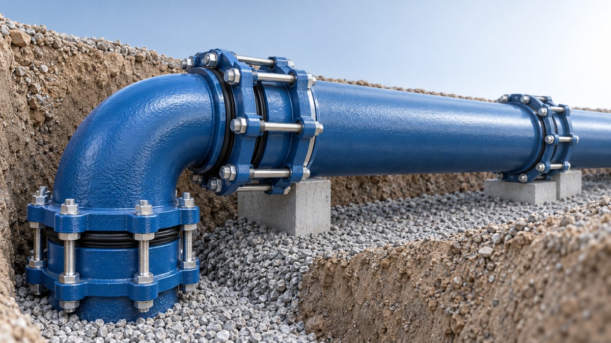
Push-in joints: efficient when the trench conditions are controlled
Push-in joints are widely used because they allow fast assembly with a rubber sealing ring and do not require bolts at every connection. When the spigot end is clean, properly lubricated, and inserted to the marked depth, this joint can provide a dependable connection while allowing a small degree of angular deflection. That deflection is useful for following a gradual route without adding unnecessary bends.
However, speed can make installers underestimate preparation. A push-in joint should not be treated as a connection that will correct poor alignment by itself. If the pipe enters the socket at an excessive angle, if stones are left under the barrel, or if the gasket is twisted or displaced, the joint may appear assembled while remaining vulnerable to leakage.
This option is generally suitable for long runs with consistent pipe dimensions, good trench bedding, and sufficient room for controlled handling equipment. It is less suitable where the pipe may be subject to pull-out force, where excavation is unstable, or where a short cut length makes it difficult to maintain alignment during assembly.
What prevents push-in joint problems
The sealing ring groove and gasket must be clean before assembly. Sand, coating debris, or a folded gasket can interfere with the seal. The spigot should be checked for damage around its chamfered leading edge, because a rough edge can drag the gasket out of position. Use the specified lubricant in an even layer; excessive or unsuitable lubricant can attract dirt or affect handling control.
After insertion, confirm the witness mark or insertion reference is positioned as intended around the circumference. A visible uneven gap is a warning that the pipe may not be seated squarely. Do not use the pipe joint to pull a badly aligned line back into place. Correct bedding and alignment first, then remake the connection.
Mechanical joints: useful where control and adaptability matter
Mechanical joints use a gasket compressed by a follower gland and bolts. They take longer to install than a push-in joint, but they offer practical benefits where installation conditions are less uniform. They are often considered for fittings, valves, repairs, transitions, and locations where installers need a connection that can be tightened in a controlled sequence.
The main site risk is uneven bolt tightening. If one side of the gland is pulled down much faster than the other, gasket compression can become uneven and the connection may not seal consistently. Tighten bolts in a balanced cross pattern, progressing around the joint rather than fully tightening one bolt at a time. This keeps the gland more even and reduces the chance of pinching or distorting the gasket.
Mechanical joints also require enough working space. A narrow excavation may leave insufficient access for installers to fit, tighten, and inspect bolts properly. Selecting this joint type without considering tool clearance can turn a repair-friendly connection into a slow and awkward installation task.
Restrained joints are about axial force, not just difficult ground
A restrained joint is selected when the pipeline must resist forces trying to pull pipe sections apart. These forces commonly develop at bends, tees, dead ends, valves, changes in diameter, and locations exposed to pressure-related thrust. Poor ground can increase the concern, but restraint should not be chosen solely because the site looks difficult. The decision should follow the anticipated force path and the ability of the installed system to resist it.
One common error is installing ordinary push-in joints at a bend and assuming backfill alone will prevent movement. If the line is pressurized before the surrounding soil has developed adequate support, or if the bedding and compaction are inconsistent, the joint may move. A restrained system provides a more direct method of carrying axial load through the pipeline, but it still requires correct assembly and compatible components.
Restraint is not automatically the best answer everywhere. It adds material and installation complexity. On a stable, straight route with an appropriate thrust-control design, it may be unnecessary. Use it where it addresses a defined movement risk, not as a substitute for proper trench preparation.
Do not separate pipe, fittings, and gaskets during selection
Joint performance depends on the complete connection: pipe socket geometry, spigot finish, gasket type, fitting interface, coating condition, and installation method. Ordering these items independently without confirming compatibility creates avoidable uncertainty on site. This is especially relevant when a project includes ductile iron pipe, fittings, and rubber sealing rings from multiple sources.
Integrated manufacturing can simplify this check because the pipe, fittings, and sealing components can be reviewed as a working connection rather than as unrelated items. Shanxi Datong Foundry Co., Ltd. produces ductile iron pipes, fittings, and rubber sealing rings through combined smelting and casting processes, which makes coordinated component selection a practical discussion point when specifying a system.
The same discipline applies to specialised ductile iron applications. For a heating distribution route, a product such as Heating Pipe should be assessed alongside its connection method, operating temperature conditions, route movement, and the fitting arrangement. The pipe material alone does not determine whether the installed joint will remain reliable.
A short pre-installation check avoids most rework
Before the first joint is assembled, confirm that the delivered pipe ends, sockets, gaskets, fittings, and joint accessories match the approved joint design. Then check the actual trench rather than relying only on the drawing. A route may have changed because of excavation conditions, utility conflicts, or access limitations.
- Identify joints near bends, valves, tees, reducers, crossings, and short pipe lengths.
- Confirm whether each location needs flexibility, bolted adjustment, or axial restraint.
- Check socket interiors, spigot ends, gaskets, bolts, and gland components for cleanliness and damage.
- Prepare bedding so the pipe barrel is supported without point loading beneath the joint area.
- Inspect joint seating or bolt tightening before backfilling hides the connection.
A suitable EN 545 ductile iron pipe joint is not simply the one with the lowest assembly time. It is the one that matches the route’s movement, thrust, access, and alignment conditions while allowing installers to make and inspect the connection correctly. Making that decision before materials reach the trench is usually the most effective way to reduce leakage risk, lost time, and repeat excavation.
Navigation
Send Us A Message

First class quality service and professional after-sales team.
Get in Touch
*We respect your confidentiality and all information are protected.