How to connect DN100 ductile iron pipe to an existing steel main
To connect DN100 Ductile Iron Pipe to an existing steel main, use a pressure-rated transition coupling approved for both measured outside diameters, or an engineered flanged transition with compatible drilling and suitable adaptors. Do not select the connection by nominal diameter alone: DN100 identifies nominal size, not a guaranteed matching outside diameter across pipe materials and standards.
During a planned tie-in, the main risks are discovering an unsuitable steel sealing surface after shutdown, installing a joint that seals but cannot resist axial movement, and ordering incompatible flanges. Confirm pipe dimensions, condition, pressure requirements, and restraint before scheduling the outage. The procedure below assumes an isolated, depressurized main; a live connection requires a separately engineered tapping arrangement.
Confirm what is actually in the ground
Existing drawings are a starting point, not proof that the exposed steel pipe matches the proposed fitting. Identify the steel pipe specification where possible, then measure its outside diameter at the intended connection location. Check several positions around the circumference and along the sealing zone to identify ovality, weld seams, corrosion, or local deformation.
For the new ductile iron pipe, obtain the manufacturer's dimensional data and joint details. Establish whether the connection will use a plain spigot, a factory-flanged pipe, or an approved flange adaptor. A socket end intended for a specific push-on joint is not automatically suitable for a universal coupling.
- Steel condition: Inspect the full gasket contact area for pitting, loose scale, coating damage, and raised weld features. Assess remaining wall thickness where deterioration is suspected.
- Operating conditions: Record normal pressure, maximum design pressure including surge, service fluid, temperature, and the proposed test conditions.
- Installation geometry: Confirm alignment, available straight pipe length, access for tightening, and space for supports or restraint.
- Material compatibility: Verify that gaskets, lubricants, coatings, and any wetted components suit the conveyed fluid and applicable project requirements.
A coupling cannot compensate for structurally unsound steel. Where corrosion leaves inadequate wall thickness or an unsuitable sealing surface, move the tie-in to sound pipe or replace the affected section before proceeding.
Choose the transition around the pipe ends
A transition coupling is often the practical choice for a straight buried tie-in because it avoids field welding where suitable plain ends are available. However, “wide range” does not mean every steel and ductile iron combination is acceptable. Obtain written confirmation that the selected fitting accommodates both actual diameters and the required service conditions.
A flanged arrangement suits accessible installations where dismantling may be needed. Matching DN markings are insufficient: two DN100 flanges can have different drilling or pressure designations. Confirm the entire interface before ordering. Where a new flange is welded to steel, use an approved procedure and qualified personnel. Do not treat direct welding between ordinary ductile iron pipe and steel as a standard field connection method.
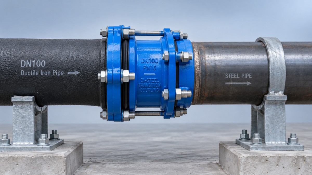
Resolve restraint before installation
A gasketed joint may be leak-tight without preventing the pipe from pulling out. Unrestrained mechanical couplings and flange adaptors must not be assumed to carry axial pressure thrust. Bends, tees, reducers, valves, and closed ends can introduce forces that require an engineered restraint arrangement.
Select a restrained transition fitting explicitly approved for both pipe materials, or provide designed anchors, thrust blocks, or another approved restraint system. Gripping elements suitable for one material may not be suitable for the other. Check the steel wall condition against the fitting manufacturer's requirements, especially where restraint transfers concentrated loads into the pipe.
Support is a separate issue. The connection should not carry unsupported pipe weight or be forced to absorb trench settlement. Prepare bedding and supports so both ends remain aligned without using coupling bolts to pull them into position.
Prepare the outage around verified components
Release the connection materials for installation only after reviewing the fitting drawings, dimensional ranges, gasket specification, bolt requirements, and installation instructions. Confirm whether assembly requires axial movement of either pipe: some arrangements cannot be fitted into a fixed gap without a suitable dismantling provision.
Establish the isolation boundary with the network operator, including backfeed paths, bypass needs, drainage, and safe access. Follow the site's isolation and lockout procedures, relieve pressure, and verify the work section is depressurized before cutting. Consider excavation stability and water ingress as part of the work plan.
Where pressure management forms part of the wider tie-in scope, a Hydraulic Control Valve may be considered separately. Confirm its intended function, rating, and installation requirements from technical documentation; it is neither a pipe transition fitting nor a substitute for verified isolation.
Install without forcing the joint
- Expose and support the connection area. Provide access around the pipe circumference and support both sections before cutting so they cannot drop, rotate, or load the new fitting.
- Prepare the pipe ends. Cut square, remove burrs, and apply the end preparation required by the pipe and fitting manufacturers. Clean sealing surfaces without reducing the pipe below permitted dimensions or damaging sound material.
- Verify the final measurements. Recheck diameters, ovality, available insertion length, and steel condition after preparation. Stop if the exposed surface falls outside the fitting's limits.
- Set alignment and engagement. Mark insertion depths where instructed and maintain the specified end gap. Keep angular deflection within the fitting's limit; do not use that allowance to accommodate avoidable misalignment.
- Assemble and tighten. Use the specified gasket lubricant where required. Tighten bolts progressively in the manufacturer's sequence with the specified torque and tool. Flanged joints require parallel faces and the correct gasket position.
- Complete restraint and protection. Install designed supports and restraint before pressurization. Restore coatings and provide approved corrosion protection without obstructing required inspection.
Do not correct poor gasket seating by repeatedly increasing bolt torque. Uneven engagement, an unsuitable diameter, or a damaged sealing surface must be corrected at its source. Similarly, pulling flange faces together with bolts can introduce stress into the pipework rather than resolve alignment.
Test the transition before returning it to service
Use the approved project or utility testing procedure, with pressure and duration established for the complete assembly. Never exceed the allowable test conditions of the lowest-rated component or the assessed limit of the existing main. Arrange the test so the transition remains accessible for inspection where the procedure permits.
Fill in a controlled manner and vent trapped air through approved points. Inspect for leakage, axial movement, uneven gasket seating, and support displacement. Keep personnel away from potential joint movement and do not tighten or dismantle a pressurized connection.
If leakage occurs, depressurize before investigation. Check insertion depth, alignment, gasket condition, sealing surfaces, and bolt tightening against the manufacturer's instructions. For potable water service, complete the required cleaning, disinfection, and acceptance steps before reconnection.
Record the installed fitting, measured diameters, restraint arrangement, torque records where required, and test results. Return the main to service gradually under the operator's procedure, then inspect the transition at operating pressure. Unexplained movement or recurring leakage is a reason to stop and reassess the connection, not to conceal it beneath backfill.
Navigation
Send Us A Message

First class quality service and professional after-sales team.
Get in Touch
*We respect your confidentiality and all information are protected.