Where to place air valves on a DN100 ductile iron pipe water main
Place air valves on a DN100 ductile iron water main at verified air-collection points and locations where filling, draining, or pressure transients require air exchange. Begin with local summits on the installed pipeline profile, then assess gradient changes, isolated sections, and pump-related low-pressure zones. Final placement must account for the hydraulic grade line and operating sequence: a geometrical high point can collect air while remaining pressurized, whereas a lower section can experience vacuum during a transient.
DN100 identifies the nominal pipe size. It does not determine air-valve spacing, connection size, or discharge capacity. Those decisions require the actual internal diameter, pipeline profile, water flow, pressure range, and intended filling and draining rates.
Locate air pockets on the installed profile
Use a longitudinal profile showing pipe crown elevations, fittings, isolation valves, pump connections, and drain outlets. Ground elevations alone are insufficient. A buried main can rise over a utility crossing and descend again without any obvious summit at ground level. Installation tolerances can also create a shallow crest that was absent from the design drawing.
A local summit is the first candidate for a combination air valve because air tends to collect at the crown. Locate the connection at the crest, with a continuous upward path into the valve. A connection positioned down the descending leg can leave an air pocket stranded above it, particularly during low-flow operation.
Changes in gradient deserve separate attention. Where an ascending main becomes less steep, or a descending main becomes steeper, the ability of water to carry air changes. Whether air accumulates there depends on flow velocity, slope, pocket size, and operating direction. Include these locations in the assessment without automatically fitting a valve at every change in slope.
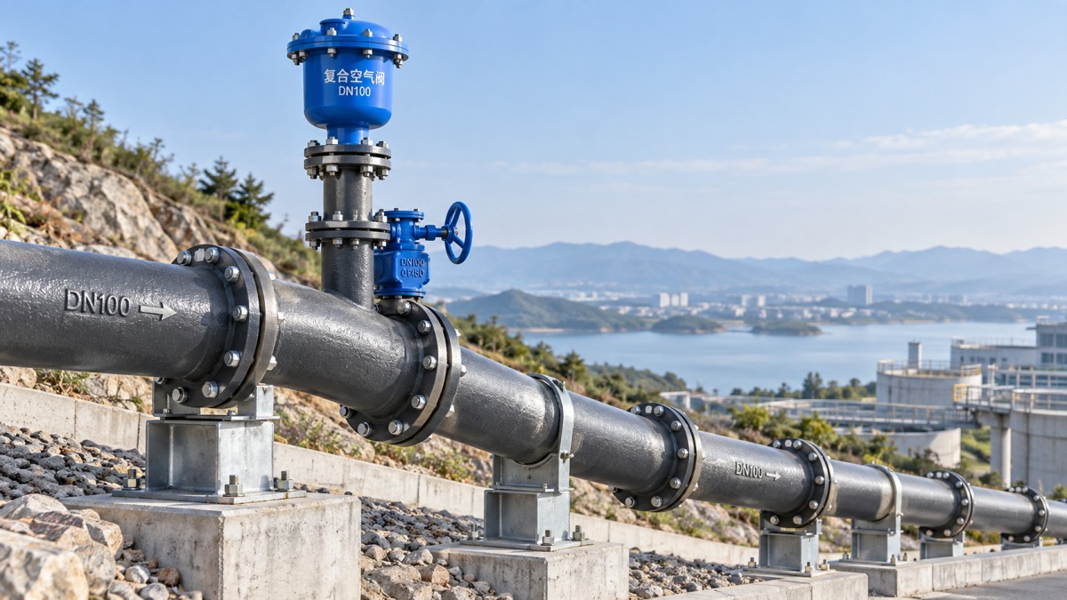
Long, nearly level reaches require similar judgment. Fixed spacing alone gives little confidence that valves will intercept air. Identify small crown-level rises and assess whether the minimum operating flow transports air toward an existing vent. A main that carries air at peak demand can retain pockets overnight when flow falls.
Match the valve function to the event
Air release during normal operation and bulk air exchange during filling or draining require different valve functions. Selecting the correct location but the wrong function leaves the original problem unresolved.
A conventional large-orifice air/vacuum valve generally closes when water arrives and is not intended to release small accumulated air pockets under pressure. A combination valve incorporates both functions. Confirm its operating characteristics from the selected valve documentation rather than relying on the product name.
Look beyond summits when assessing vacuum
Compare the hydraulic grade line with the pipe elevation for normal operation, minimum supply pressure, and planned shutdown conditions. Where the grade line approaches the pipe elevation, the pressure margin is small. Pump trips, rapid valve movements, or a draining water column can then produce subatmospheric pressure.
Steady-state calculations do not establish the lowest pressure during a transient. A pump discharge area, for example, warrants assessment when loss of pumping creates a pressure drop and column separation. Valve placement must reflect pump behavior, check-valve closure, downstream elevation, and other surge-control provisions. Simply adding an air valve immediately after every pump is not a reliable design rule.
Air admitted during a low-pressure event changes the later pressure response. When flow recovers, rapid expulsion of that air and abrupt valve closure can generate a pressure surge. Controlled exhaust or an anti-slam arrangement should therefore be evaluated where the transient analysis indicates this sequence. Restricting exhaust also affects filling time, so the selected arrangement must satisfy both conditions.
For planned draining, trace the air path from each valve to the drain outlet with isolation valves in their intended positions. A high-point valve on the opposite side of a closed isolation valve cannot protect the section being emptied. A main with several separately drainable sections can require several air-admission locations even when its overall profile has only one prominent summit.
Size from airflow and allowable pressure difference
During controlled filling, the displaced air volume is approximately the incoming water volume before compression effects become significant. During draining, air must replace the outgoing water fast enough to keep the internal pressure within the design limit. Establish the intended water rates first, then select the air valve from its published performance curves.
Use the actual pipe bore when converting flow to water velocity. Nominal DN100 dimensions do not fully describe the internal area because wall thickness and lining affect it. Likewise, the valve connection designation does not identify its effective air orifice.
Airflow curves must be interpreted at the relevant pressure difference and stated reference conditions. A quoted capacity for free air cannot be directly compared with compressed air volume inside a pressurized main without conversion. Confirm inlet and exhaust performance separately; one capacity figure does not establish both.
The branch connection, isolation valve, riser, and any inlet or outlet accessories form part of the airflow path. A restricted branch can govern the capacity of a larger air valve. Keep the connection appropriately sized and avoid unnecessary bends or fittings that increase losses or retain water.
Make the connection accessible and suitable for water service
Connect the assembly to the pipe crown through a compatible tee or an approved tapping arrangement for the particular ductile iron pipe. Confirm the tapping limits, lining details, pressure rating, and joint arrangement before installation. Support the valve and riser so their weight and maintenance loads do not place excessive bending stress on the branch.
Fit an accessible isolation valve below the air valve to permit servicing. Its normal operating position must allow the required airflow. Record that position clearly: an air valve isolated after maintenance provides no protection even though the assembly remains visibly present.
Material identification alone does not establish suitability. A ductile iron product listed as Heating Pipe still requires confirmation of water-service suitability, lining, dimensions, pressure rating, and connection details before inclusion in this main.
The chamber must provide access for removal, adequate drainage, and a clean route for admitted air. Air/vacuum valves draw outside air into the pipeline, so a flooded chamber creates a contamination pathway. Any protective vent arrangement must preserve the airflow capacity used in sizing. Screens and protective accessories also need access for inspection and cleaning.
Verify the placement during commissioning
Fill each section at the rate used in the valve assessment, with its intended vents available. Observe whether bulk air escapes before water reaches the valve and whether the valve closes without leakage or abrupt pressure changes. Persistent air symptoms downstream of a functioning valve can indicate an unrecognized crest, insufficient transport velocity, or a restricted connection.
Record the installed crown elevations, valve functions, orifice details, branch sizes, isolation positions, and approved filling and draining sequences. These records matter when later changes introduce different flow directions or new isolation boundaries. A valve location that served the original operating arrangement can become ineffective after the main is reconfigured.
Navigation
Send Us A Message

First class quality service and professional after-sales team.
Get in Touch
*We respect your confidentiality and all information are protected.