How to verify wall thickness tolerances on K9 ductile iron pipe
To verify wall thickness tolerances on K9 ductile iron pipe, establish the specified nominal thickness and permitted negative deviation for the pipe’s nominal diameter, then compare validated metal-thickness measurements with the resulting acceptance limit. A K9 marking alone does not establish that limit, and a single satisfactory reading cannot represent the whole pipe.
The inspection must connect three things: the purchase specification, the manufacturer’s dimensional requirements, and measurements taken using a suitable method. Keeping those connections clear prevents two common errors: rejecting acceptable manufacturing variation and accepting a locally thin wall because the average thickness looks satisfactory.
Establish the acceptance limit before measuring
K9 is a wall-thickness class designation, not a statement that every pipe has a nine-millimetre wall. The nominal thickness depends on nominal diameter and the dimensional rules in the applicable specification. The permitted manufacturing deviation is a separate requirement.
Start with the purchase order, approved technical specification, and manufacturer’s inspection documentation. Identify the governing standard and edition, the nominal diameter, the thickness class, and any project-specific dimensional requirements. Different specifications may use different classification systems, so a pressure-class designation should not be treated as interchangeable with K9 without an approved technical basis.
Your inspection sheet should contain:
- The pipe identification and its connection to the delivery lot or manufacturing records.
- The specified nominal diameter and K9 designation.
- The nominal metal-wall thickness from the applicable dimensional requirements.
- The permitted negative deviation and any specified upper limit.
- The measurement method, sampling requirements, and acceptance decision rule.
Where the specification defines a nominal thickness and a negative allowance, the basic calculation is:
Minimum permitted metal thickness = specified nominal thickness − permitted negative allowance.
Apply the allowance exactly as written. Do not replace a dimensional allowance with an assumed percentage, or apply a pipe-barrel requirement to a socket or other specially shaped section. If the specification expresses acceptance differently, use that definition rather than forcing it into this calculation.
The nominal value is not automatically the rejection threshold. Equally, a permitted negative deviation does not authorize additional deductions for measurement uncertainty, surface condition, or suspected casting variation.
Measure the iron wall, excluding lining and coating
The wall thickness being checked is the ductile iron itself. Cement mortar lining and external protective coatings serve different purposes and should not be counted as structural metal thickness.
A direct mechanical measurement can be useful where both metal surfaces are accessible, such as at an approved exposed end or prepared reference section. Use an instrument with suitable contacts for the curved surfaces. A reading that includes lining, coating, burrs, or an irregular edge will not represent the metal wall correctly.
End measurements also have a coverage limitation: they describe the accessible end, not the full barrel. They can support an ultrasonic check, but they cannot establish thickness throughout the pipe.
Ultrasonic thickness testing is practical for checking multiple locations along the barrel from the outside. However, ductile iron requires attention to material response. Its graphite structure can scatter and attenuate ultrasound, and casting texture can make coupling inconsistent. Select a probe and instrument setup that produce a clear, repeatable back-wall response on the pipe being examined.
Do not rely on a generic steel velocity setting. Validate the setup against representative ductile iron with independently established thickness, preferably covering the expected measurement range. The reference should reasonably reflect the material and surface conditions under inspection.
Make the ultrasonic readings repeatable
Check instrument calibration status and verify the complete measurement setup before inspection. A current calibration certificate does not, by itself, prove that the selected probe, sound velocity, and surface preparation produce correct readings on this material.
Prepare each location sufficiently to obtain reliable coupling. Loose material and contamination can interfere with the signal. Where the procedure requires local coating removal, control that work and restore the protective system afterward. Measuring through a coating is acceptable only when the selected technique has been validated to exclude its contribution.
Use a suitable couplant and stable probe contact. Repeat readings at the same location and slightly reposition the probe to assess consistency. Large changes caused by small movements need investigation before the displayed value becomes an acceptance result.
A missing or unstable back-wall echo is not proof of a thin wall. It may result from poor coupling, rough surfaces, unsuitable probe selection, or material attenuation. Where available, review the waveform to confirm that the instrument is measuring the intended echo. Recheck the reference during the inspection and at completion to detect drift or setup changes.
If the pipe surface temperature differs significantly from the reference conditions, account for that through the approved procedure. Temperature can affect both instrument performance and the sound velocity used to calculate thickness.
Distribute inspection points around and along the barrel
A useful measurement plan checks circumferential and longitudinal variation. Readings confined to one side or one end can miss a thinner area elsewhere. Use the sampling frequency required by the contract or inspection plan; distinguish between how many pipes are selected and how extensively each selected pipe is examined.
On each selected pipe, establish measurement stations along the barrel and take readings at distributed positions around the circumference. Identify positions using a consistent orientation and distance from a defined end. This makes a low reading easy to locate again and allows the manufacturer’s representative to examine the same area.
Keep barrel measurements clear of sockets, transitions, and other geometries unless those locations have their own defined inspection requirements. Curvature and changes in section can affect ultrasonic interpretation as well as the applicable dimensional limit.
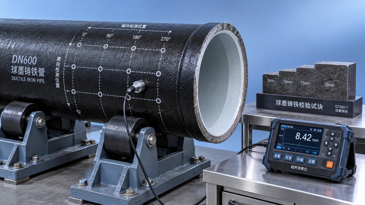
Include targeted checks around suspicious surface features, handling damage, or unexpectedly low readings. These checks supplement the planned coverage. When a low value appears, measure nearby points closely enough to determine whether it is isolated or part of a broader thin region.
Safe access matters to measurement quality. Secure pipes against rolling, use stable supports, and reposition them through controlled handling. An inaccessible lower quadrant should prompt a handling adjustment rather than an undocumented gap in coverage.
Judge low readings without averaging them away
Assess results against the acceptance rule specified for the product. Where that rule sets a local minimum thickness, higher readings elsewhere do not compensate for a confirmed reading below the limit. An average can describe manufacturing consistency, but it cannot replace a local minimum requirement.
For an unexpectedly low result, repeat the measurement after checking coupling, probe position, surface condition, and instrument settings. Confirm it with another suitable probe or an independent method where practical. Preserve the original reading and subsequent findings so the investigation remains traceable.
Results close to the limit need an agreed decision rule that accounts for measurement uncertainty. Display resolution is not the same as accuracy: a gauge showing several decimal places may still have uncertainty large enough to affect the decision. Do not round a borderline value upward simply to obtain a pass.
Separate three outcomes in the record: accepted measurements, confirmed nonconformity, and locations where a valid measurement could not be obtained. An invalid signal is not a passing result. Hold affected pipes from installation while their status is resolved through the established quality process.
Keep the release decision traceable
Record individual readings and locations, the applicable limits, instrument and probe identification, setup verification results, surface preparation, and any repeat measurements. Connect those records to the pipe identification and delivery documentation. Photographs can help locate investigated areas, but they should supplement the measurement map.
For deliveries from an integrated manufacturer such as Shanxi Datong Foundry Co., Ltd., which produces ductile iron pipes, fittings, and rubber sealing rings, maintain separate acceptance requirements for each component type. A fitting such as a Sludge Discharge Tee has different geometry from a straight pipe barrel; its thickness inspection should follow the applicable fitting specification and approved drawing.
Passing a wall-thickness inspection supports dimensional acceptance. Installation release also depends on the other required checks, including joint condition, lining and coating integrity, and delivery damage. Release the pipe when the specified measurements are valid, the results meet the acceptance criteria, and any exceptions have a documented disposition.
Navigation
Send Us A Message

First class quality service and professional after-sales team.
Get in Touch
*We respect your confidentiality and all information are protected.