How to prepare a cut end of K9 ductile iron pipe for joint assembly
A cut end of K9 ductile iron pipe is ready for joint assembly only when its diameter suits the joint, the cut is square, the edge has the required profile, and the sealing surface is clean and sound. Removing the obvious burrs is only part of the job. A sharp corner can damage the rubber sealing ring, while an oversized or oval end can prevent correct insertion even after careful grinding.
Before cutting, establish which joint will receive the new end. A standard push-in socket, a mechanical joint, and a restrained connection can require different preparation. The K9 designation describes the pipe’s wall-thickness class; it does not specify a universal chamfer, insertion depth, or restraint arrangement.
Check whether the proposed cut location can form a suitable spigot
A factory spigot is made to fit its mating socket. Cutting farther along the barrel creates a new spigot, but that section must still meet the joint’s outside-diameter and ovality limits. Do not assume that every position along every pipe is suitable for cutting.
Use the pipe supplier’s cutting designation and joint dimensions to select the location. Where dimensional checks are required, measure around the proposed cut and across several directions. A circumference measurement helps assess diameter, but it will not reveal ovality by itself. The section entering the socket must remain within tolerance throughout the required engagement length.
Inspect this area for dents, deep scores, casting irregularities, and damaged lining. Grinding an oversized barrel down until it enters the socket is not an acceptable field correction: it can reduce wall thickness and create an uneven sealing surface.
For a restrained joint, establish how the restraint engages the pipe before proceeding. Some designs require a special spigot feature, locking component, or approved field preparation. A plain cut end with a chamfer does not automatically replace a factory restrained spigot.
Make a square cut without damaging the pipe or lining
Support and secure both the retained pipe and the offcut so neither can roll, drop, or pinch the cutting tool. For an existing pipeline, isolate, depressurize, and drain it before work begins. Keep the cutting area clear and use protection appropriate to flying particles, noise, and dust from the pipe, coating, and lining.
Mark the cut around the full circumference using a pipe wrap or suitable marking guide. A line drawn across only the visible upper surface can lead to a sloping cut. Use cutting equipment suitable for ductile iron and follow its operating instructions; improvised heating or uncontrolled flame cutting can damage the surrounding material and protective layers.
As the cut finishes, support the offcut rather than breaking the remaining section away. Breaking it can tear the edge or chip the internal lining. Remove loose debris, then check the end face against the pipe axis. An uneven cut can make the insertion mark misleading and leave one side of the end closer to the socket’s internal limit than the other.
Remove burrs and form the correct lead-in profile
Deburring and chamfering serve different purposes. Deburring removes sharp fragments left by cutting. Chamfering forms the lead-in that allows the spigot to pass through the gasket without cutting, dragging, or displacing it.
Remove burrs from the outside edge and from exposed metal at the bore. Work carefully around cement-mortar or other internal lining: loose lining must be addressed, but sound lining should not be ground away simply to make the bore edge look uniform.
For a push-in joint, form the external chamfer to the profile specified for that pipe size and socket design. There is no single bevel angle or length suitable for every K9 pipe joint. Use the joint preparation drawing or the designated profile gauge. An intact factory spigot from the same pipe and joint system can provide a useful visual comparison.
Work evenly around the circumference. The finished lead-in should have a smooth transition into the barrel, without sharp points, steps, or isolated flat spots. Avoid extending the grinding into the cylindrical surface where the gasket seals. An excessively long or deep bevel can remove material needed for proper engagement.
Mechanical joints and couplings may require a different edge treatment. Apply their specified preparation rather than automatically copying a push-in spigot chamfer.
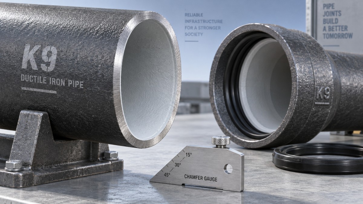
Check the complete circumference under good lighting. A chamfer that looks correct from above may still have a sharp section underneath. Use a suitable inspection aid rather than running bare fingers along freshly cut metal.
Repair exposed surfaces before they enter the joint
Cutting and grinding expose metal and can damage adjacent external coating or internal lining. Clear away swarf, abrasive particles, dust, and loose coating before assessing the repair area. Contamination left on the spigot can enter the gasket contact zone during insertion.
Repair exposed metal and damaged coating with the system specified for the pipe and conveyed medium. Internal lining repairs require compatible materials and sound edges around the damaged area. Loose, cracked, or detached lining needs repair before assembly; inserting the end into the socket does not stabilize it.
Keep the repaired surface smooth, particularly where the gasket will contact the pipe. Thick coating ridges, runs, or lumps can interfere with the seal or increase insertion resistance. Allow repair materials to reach the required condition for assembly before applying lubricant or moving the pipe into the socket.
If the installation uses Pre-insulated Ductile Iron Pipe (Thermal Piping), cutting also affects the insulation and outer protective layer. Establish the required exposed carrier-pipe length and joint closure arrangement before cutting. Preparing the ductile iron end and reinstating the insulation are separate tasks, and both must suit the connection.
Restore the insertion mark and prepare the mating socket
The original insertion mark no longer applies after shortening the pipe. Measure from the newly prepared end and mark the insertion position specified for the joint. Make the mark visible during assembly so it can reveal uneven insertion or movement after alignment.
Do not use the socket bottom as an improvised depth stop. The intended assembly position can include clearance for movement or joint geometry. Pushing until the pipe cannot travel farther may exceed that position.
Clean the socket and gasket seat, then check the sealing ring for cuts, distortion, embedded grit, and correct seating. Use the gasket and lubricant specified for the joint and service. Apply lubricant to the surfaces directed by the assembly instructions; excess lubricant cannot compensate for an unsuitable diameter or rough chamfer.
Align the pipe and socket before insertion. Where the joint permits angular deflection, assemble it in the prescribed aligned position before applying that deflection. Forcing the cut end into a misaligned socket can load one side of the gasket and hide a preparation defect.
If insertion becomes difficult, stop and inspect
Some resistance is expected as the spigot engages the gasket, but a sudden stop, uneven entry, or unexpectedly high force needs investigation. Increasing force immediately can turn a correctable preparation problem into a damaged sealing ring.
- The end catches at first contact: check alignment, the full chamfer, and gasket seating.
- Resistance rises as the barrel enters: check outside diameter, ovality, coating buildup, and lubrication.
- The insertion mark approaches unevenly: check pipe alignment, cut squareness, and assembly-tool positioning.
- The gasket moves or appears at the socket mouth: withdraw the pipe and inspect the ring before reassembly.
After withdrawal, inspect the gasket for damage and replace it if necessary. Correct the cause before trying again. Extra pulling force is not a repair for an oversized end, a sharp edge, or a displaced ring.
Before releasing the assembly equipment, check the insertion position around the pipe and complete any restraint components required by the connection. Keep a record of cut-end preparation and repairs where the project requires it. The completed pipeline still needs its specified inspection and pressure testing: a joint that slides together smoothly has passed an assembly check, but its sealing performance must be assessed as part of the installed system.
Navigation
Send Us A Message

First class quality service and professional after-sales team.
Get in Touch
*We respect your confidentiality and all information are protected.