Double-Socket Sleeve Selection: Pipe OD, Seals, and Pressure Ratings
A double-socket sleeve should be selected by the actual outside diameter of both pipe ends, the approved pipe-and-gasket combination, and the pressure capability of the complete joint—not by nominal diameter alone. On a ductile iron pipeline, two components carrying the same DN designation can still be unsuitable for connection if their dimensional standards, joint profiles, or tolerances differ.
This becomes important when replacing a damaged section, connecting pipe from different sources, or closing a gap between fixed pipe ends. An unsuitable sleeve may resist assembly, damage the gasket, or leak after pressurization. Start by confirming dimensional compatibility, then check seal suitability, pressure limits, and whether the installation requires axial restraint or a sleeve that can slide fully over a pipe end.
Establish the connection type before comparing dimensions
“Double-socket sleeve” generally describes a fitting with a socket at each end, but the name does not establish the joint design. Confirm whether the proposed fitting uses push-in gaskets, mechanical compression, or another arrangement. Also establish whether it has an internal stop. A stopped sleeve may suit assembly between movable pipe lengths but cannot automatically serve as a sliding repair sleeve between fixed ends.
For a repair connection, check that sufficient straight, sound pipe is exposed for installation and that the fitting can reach its final position without leaving either pipe end insufficiently engaged. Angular movement, permitted end gap, and insertion depth must come from the specific joint drawing or installation instructions.
Where access or assembly constraints suggest a different fitting, a listing such as Straight Split Sleeve can be included in the technical review. The product name alone does not establish equivalence: obtain its construction details, pipe compatibility, seal arrangement, and pressure documentation before considering it an alternative.
Check the pipe OD at the sealing location
Nominal diameter identifies a size designation, not a complete dimensional specification. Request the sleeve’s approved pipe outside-diameter range and the applicable pipe standard. Check both pipe ends separately, especially where the connection involves existing pipe, different manufacturing origins, or different pipe materials.
- Prepare the measurement area. Remove loose deposits and contamination without damaging the pipe or removing sound protective coating unnecessarily.
- Measure the intended sealing zone. Use a suitable diameter tape or calibrated measuring equipment. A circumference-based diameter reading alone will not reveal local ovality.
- Assess out-of-roundness. Check diameters in multiple orientations and inspect for dents, casting irregularities, or deformation near cut ends.
- Compare against documented limits. Both the measured OD and ovality must satisfy the approved joint requirements; a gasket should not be expected to compensate for an unapproved mismatch.
Coating thickness and condition also matter. A thick repair coating, corrosion buildup, or a rough sealing surface can affect assembly and gasket contact. Do not grind a pipe down to fit without an approved procedure; that may compromise wall thickness or protection.
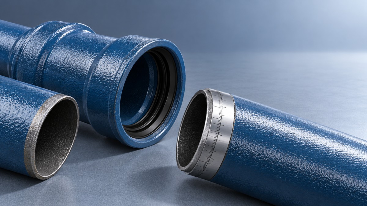
Ask for a sectional joint drawing showing the gasket seat, socket depth, required pipe-end preparation, and insertion reference. Socket mouth diameter alone does not describe the sealing geometry. For cut pipe, confirm the required end squareness and chamfer rather than copying the appearance of an unrelated joint.
Match the seal compound and its geometry
A seal must be compatible with both the conveyed medium and the socket profile. Two rings made from the same elastomer are not interchangeable merely because their nominal sizes match. Cross-section, hardness, manufacturing tolerances, and the intended compression or lip-sealing action are part of the joint design.
These are screening considerations, not material approvals. A generic statement such as “oil-resistant rubber” is insufficient when the fluid composition is uncertain. Wastewater, for example, may contain constituents that change the seal assessment.
Check the installation lubricant as well. It must be approved for the gasket, pipe coating, and service. An incompatible lubricant can affect elastomer performance; inadequate lubrication can cause the ring to roll, twist, or move during insertion. Request seal identification and traceability so the delivered rings can be matched to the approved specification.
Read pressure ratings as limits with conditions
A pressure designation on the fitting is not, by itself, proof that the assembled connection is suitable. Establish the allowable operating pressure of the specific sleeve, gasket, pipe combination, and joint configuration at the intended temperature. The connection is limited by its lowest-rated applicable element.
Keep the following pressure conditions separate when reviewing supplier documentation:
- Sustained operating pressure: the service pressure, including static head at the fitting location.
- Transient pressure: the maximum pressure associated with pump trips, valve operation, or other hydraulic events.
- Site test pressure: the permitted pressure and procedure for the installed assembly, which may differ from a factory component test.
Do not assume a stated PN value automatically covers every surge or test condition. Request the declared operating, maximum, and test limits under the applicable product standard, including temperature restrictions. Where surge pressure has not been established, hydraulic assessment is needed before approving the connection. Repeated pressure cycling may also require specific confirmation rather than comparison with a single peak value.
Negative pressure needs separate attention. A joint suitable for positive internal pressure should not automatically be accepted for vacuum service or conditions where groundwater could enter during depressurization. Obtain confirmation where those conditions are credible.
Separate sealing capability from axial restraint
A watertight socket joint is not necessarily a restrained joint. Internal pressure can generate axial forces at bends, branches, closed ends, and changes in section. An ordinary unrestrained sleeve should not be credited with resisting those forces unless its approved design explicitly provides that function.
Review the pipeline restraint arrangement independently of the seal selection. Depending on the design, this may involve thrust blocks, anchors, restrained joints, or another engineered provision. Soil conditions, excavation, and proximity to an existing anchor can affect the assessment; pressure rating alone does not settle it.
Likewise, permitted angular deflection is not an allowance for arbitrary misalignment. Assemble and deflect the joint only as instructed, maintaining the required engagement on both sides. Settlement, vibration, or thermal movement must remain within the documented joint limits throughout service.
Make approval depend on verifiable documents
Before releasing a sleeve for purchase, assemble a comparison sheet containing the measured pipe dimensions, joint drawing, exact gasket specification, pressure limits, installation requirements, and restraint assumptions. Identify the applicable pipe, fitting, and elastomer standards by designation and edition where the project requires them. A general claim of standards compliance should not replace confirmation that the proposed components are compatible.
Resolve discrepancies before installation. If OD is outside the approved range, select a fitting documented for that range or an appropriate transition arrangement. If pressure capability is unclear, obtain written confirmation for the exact assembly. If fixed pipe ends prevent the specified insertion sequence, change the fitting arrangement rather than reducing engagement.
During installation, record insertion marks and inspect accessible gasket seating indicators before testing. Conduct the site pressure test using the approved project procedure, with the required restraints in place. A successful test verifies the installed assembly under those test conditions; it does not validate an undocumented material substitution or extend the joint’s approved operating limits.
Navigation
Send Us A Message

First class quality service and professional after-sales team.
Get in Touch
*We respect your confidentiality and all information are protected.