Thermal Piping Expansion: Planning Anchors, Guides, and Flexible Joints
Thermal piping design succeeds when movement and restraint are planned together. Anchors establish fixed points, guides control the direction of travel, and flexible joints accommodate only the movements their construction permits. A joint that allows angular deflection is not automatically an axial expansion joint, and a rubber-sealed connection is not automatically capable of resisting pressure thrust.
For ductile iron systems, this distinction is critical: sealing, flexibility, and axial restraint are separate functions. The layout must provide a continuous load path while keeping pipe displacement, joint withdrawal, anchor reactions, and gasket conditions within documented limits.
Calculate movement from the installed condition
The starting calculation for an unrestrained straight pipe is:
ΔL = α × L × ΔT
Here, ΔL is the change in length, α is the material’s coefficient of linear thermal expansion, L is the effective length between movement-control points, and ΔT is the change in pipe-wall temperature. Use the coefficient specified for the supplied material rather than treating all metallic piping as equivalent.
For illustration, a 60 m run with an assumed coefficient of 11 × 10−6/K and a 50°C temperature increase would expand by approximately 33 mm if unrestrained. This is a calculation example, not a material specification or a joint-movement allowance.
The reference temperature should be the pipe temperature when anchors are secured and joint insertion positions are set. A line installed near its highest operating temperature may need substantial contraction capacity rather than additional compression capacity. Assess the minimum and maximum pipe-wall temperatures, including shutdown, empty-pipe solar exposure, cleaning, and commissioning conditions where applicable.
Buried and exposed sections also behave differently. Soil interaction distributes restraint along buried pipe; it does not make thermal strain disappear. At transitions to chambers, bridges, buildings, or exposed pipe racks, the change in restraint can concentrate displacement and loads. A free-expansion calculation alone cannot establish those interface forces.
Distinguish joint flexibility from usable axial travel
A ductile iron push-on joint can provide sealing and angular accommodation without being designed as a telescopic expansion device. Its allowable deflection, insertion requirements, and resistance to separation depend on the specific joint design. Restrained joints add axial load-transfer capability, but they should not be treated as either perfectly rigid connections or freely sliding joints.
A movement assessment must distinguish between:
- Angular deflection: rotation between connected pipe sections, subject to the permitted joint angle.
- Axial travel: controlled insertion or withdrawal within documented operating limits.
- Axial restraint: resistance to separation through locking components, tie rods, anchors, or another engineered mechanism.
These capabilities are not interchangeable. Do not calculate available thermal travel by multiplying the number of gasketed joints by an assumed socket clearance. Friction, installation variation, restraint engagement, and alignment can cause movement to concentrate at only a few joints.
Where an expansion coupling or another purpose-designed flexible assembly is selected, obtain its pressure-rated movement envelope. Confirm whether axial, angular, and lateral capacities can be used simultaneously; the maximum value for each direction may not be available in combination. Also distinguish service movement from installation adjustment.
Place anchors around a defined load path
An anchor fixes the piping at a designated location and transfers the resulting forces into a supporting structure or foundation. Its position determines which pipe length feeds thermal movement into each flexible element. Adding anchors without checking compatibility can trap a section that has no adequate means of accommodating strain.
A straight movement zone might comprise a fixed point, guided pipe, an expansion assembly, and another fixed point. The actual arrangement must match the assembly design: some devices need main anchors that resist pressure thrust, while tied or pressure-balanced configurations change the external reactions and permitted movement.
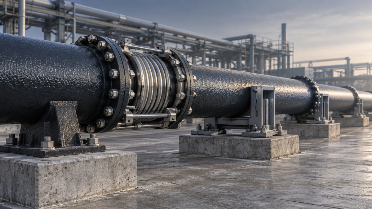
Anchor design should consider pressure thrust, support friction, flexible-element resistance, restraint engagement, and applicable transient or occasional loads. These effects must be combined according to their directions and governing load cases, rather than simply added as unrelated maximum values.
Pressure thrust across an unrestrained expansion assembly can dominate the reaction:
F = P × Aeffective
At 1 MPa, an illustrative effective pressure diameter of 400 mm produces approximately 126 kN of thrust. For a bellows, the effective area is established by its geometry and manufacturer’s data; it should not automatically be replaced with the pipe bore area.
Pressure thrust also arises at bends, tees, reducers, and closed ends. A flexible connector near a bend does not remove the need to resolve those forces. Likewise, a thrust block intended to resist hydraulic forces should not be assumed suitable as a thermal anchor without checking its stiffness, bearing conditions, and load direction.
Use guides to preserve the intended movement
A guide permits movement along the intended axis while limiting lateral displacement. A sliding support carries weight while allowing travel. An anchor restrains designated movement. Confusing these functions can turn an apparently flexible layout into an overconstrained system.
Guides are particularly important beside axial expansion devices, where lateral instability or misalignment can damage the assembly. Guide positions and spacing should follow the selected device’s instructions and the piping stability assessment. A spacing rule developed for a particular metallic bellows arrangement is not automatically valid for a telescopic coupling or gasketed ductile iron line.
Check clearances against both calculated displacement and construction tolerances. Excessive clearance can allow harmful sideways movement; insufficient clearance can cause binding. Sliding friction also contributes to anchor loads and can change with corrosion, contamination, wear, or bearing-pad condition.
Supports must carry the full operating weight without transferring unintended bending into the flexible joint. Where a pipe connects to a pump, vessel, or wall penetration, confirm that the proposed restraint arrangement protects that interface rather than merely relocating movement toward it.
Keep gasket qualification separate from movement qualification
Rubber seals must remain compatible with the conveyed fluid, pipe-wall temperature, pressure, and any cleaning or disinfection exposure. Elevated temperature affects more than expansion: it can alter elastomer aging, compression set, and the sealing margin available during joint movement.
A product designation such as Rubber Ring3 does not establish the compound, temperature rating, or approved joint compatibility. Those properties require a material specification and supporting documentation for the intended connection. A seal should not be credited with axial travel or thrust resistance simply because it fits the socket.
Where repeated movement is expected, request evidence covering the complete joint under the relevant pressure, temperature, displacement, and cycling conditions. Elastomer material qualification alone does not demonstrate the performance of a moving joint assembly.
Apply standards to the correct part of the assessment
For ductile iron water pipelines, relevant references can include ISO 2531 or EN 545 for pipe, fittings, accessories, and associated joint requirements, depending on the specified system. ANSI/AWWA C111/A21.11 addresses rubber-gasket joints for ductile iron pressure pipe and fittings, while ANSI/AWWA C600 addresses installation of ductile iron water mains and their appurtenances. EN 681-1 addresses vulcanized rubber seals for water and drainage applications.
These documents have different scopes. Compliance with a pipe or gasket standard does not, by itself, approve a particular expansion-joint arrangement or anchor layout. Confirm the contractually applicable editions, service limitations, local requirements, and manufacturer’s installation instructions. Where metallic bellows are used, EJMA guidance may support their assessment, but it is not a universal design method for every flexible connector.
A reviewable design should connect the temperature cases to calculated movement, the movement to documented joint capacity, and the resulting forces to verified supports and foundations. Installation drawings should state anchor and guide functions, joint setting dimensions, reference temperature, and allowable tolerances. Commissioning inspection should then confirm those conditions—including removal of temporary restraints where required—before pressure and temperature changes test the intended load path.
Navigation
Send Us A Message

First class quality service and professional after-sales team.
Get in Touch
*We respect your confidentiality and all information are protected.