Flange vs Mechanical Joint: Which Fits Buried Water Main Connections?
A valve connection may look straightforward on a drawing: two pipe ends, a joint, and a pressure rating. Underground, the decision becomes less forgiving. Settlement, groundwater, restricted bolt access, and hydraulic thrust can turn an apparently interchangeable connection into a maintenance problem.
Choosing between flange vs mechanical joint connections for a buried ductile iron water main therefore requires more than matching nominal diameters. Flanges provide rigid, bolted interfaces; conventional mechanical joints provide a gasketed connection with limited angular flexibility but do not inherently resist axial separation. For most buried-main applications, mechanical joints are the more adaptable starting point at fittings and valves. Flanges remain useful where equipment interfaces, structural support, and access justify them.
The first distinction: sealing is not restraint
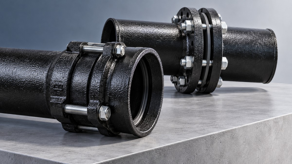
A flanged joint seals by compressing a gasket between two mating flange faces. Bolts hold the assembly together and transfer axial load across the connection. That does not mean the joint should carry unsupported equipment weight, tolerate pipe misalignment, or absorb differential settlement. Its rigidity makes support and alignment especially important.
A mechanical joint uses a socket, rubber gasket, gland, and bolts. Tightening the gland compresses the gasket into the sealing space around the plain pipe end. Within the manufacturer’s limits, the assembly can accommodate angular deflection, making it better suited to modest alignment changes than a rigid flange.
A standard mechanical-joint gland is not an axial restraint device. At bends, tees, dead ends, and closed valves, pressure can generate forces that pull an unrestrained joint apart. The design must address those forces through engineered thrust blocks, approved restrained-joint systems, or another verified restraint arrangement.
Where the buried-main decision usually lands
Direct burial with normal alignment adjustments
Mechanical joints are commonly preferred at buried ductile iron fittings and valves because installers can make limited alignment adjustments without forcing rigid faces together. This is useful when a trench follows an existing utility corridor or a replacement section must meet an established pipeline.
The flexibility has boundaries. Allowable deflection depends on joint design, size, and manufacturer instructions. It is not a universal angle, nor permission to bend the assembly until it fits. Follow the specified insertion and deflection sequence, and confirm whether an added restraint device changes the permitted movement.
Connections inside a chamber or vault
Flanges become attractive when valves, meters, or other equipment need a defined bolted interface within an accessible structure. The arrangement allows inspection and disassembly, provided there is clearance to remove bolts and withdraw the component.
For equipment such as a Ball Valve, evaluate the actual end connection, face-to-face dimensions, pressure rating, and operating loads rather than assuming that every valve suits either joint type. Equipment weight and actuator loads may require dedicated supports.
Direct-buried flanges specified by the owner
A buried flange is not automatically unacceptable. It may be required at a particular equipment interface or by an established utility detail. However, confirm that the governing specification permits it and resolve corrosion protection, bedding, support, and future excavation access before approval. A flange buried without these provisions loses much of its practical serviceability advantage.
Four checks that can overturn an initial preference
1. Movement at structural transitions
The riskiest location is often where the pipe leaves a rigid concrete chamber and enters backfill. The structure and surrounding soil may settle differently, concentrating loads near the wall penetration or first joint.
A mechanical joint offers limited angular accommodation, but it does not make a poorly supported transition safe. Assess bedding, compaction, groundwater, expected displacement, and any need for an engineered flexible arrangement. Avoid treating joint flexibility as a substitute for geotechnical judgment.
2. The complete thrust load path
At a valve or change of direction, identify where pressure forces go. A flanged valve connected to short flanged spools may resist separation locally while transferring the load to an unrestrained connection farther along the line.
Similarly, adding a restrained gland to one mechanical joint does not necessarily restrain the entire assembly. Required restrained lengths depend on pressure, pipe size, fitting geometry, cover, soil conditions, and the restraint design method. Include surge and test conditions where applicable. If using thrust blocks, verify bearing conditions and required concrete strength before testing.
3. Corrosion exposure around the joint
Both options introduce metallic components that need a project-specific corrosion strategy. Flanges have bolts, nuts, faces, and crevices; mechanical joints have glands and fasteners. Neither configuration is inherently immune to aggressive soil or groundwater.
Specify compatible fastener materials and the required coatings, encasement, or other protective measures. Where cathodic protection or electrical isolation is involved, coordinate the joint detail with the corrosion design. Protective systems should be inspected after assembly and repaired where installation damages them.
4. Real installation and removal space
Flanges need accurate face alignment and access for controlled bolt tightening. Pulling misaligned pipework together with flange bolts can introduce damaging stress. Mechanical joints also need working room around the gland and suitable tools; a narrow trench does not eliminate that requirement.
For either connection, consider the future repair sequence. Can workers reach the lower bolts? Can the valve be removed without shifting a long pipe run? Flanges are detachable, but they do not automatically provide the axial clearance needed for dismantling.
What the procurement specification should actually say
“Ductile iron, mechanical joint” or “flanged, suitable for water” is not enough to establish compatibility. Technical evaluators should require the following information:
- Dimensional system: Confirm pipe outside diameter, socket dimensions, flange drilling, facing, and applicable manufacturing standards. Matching nominal sizes alone is insufficient.
- Pressure basis: Check the complete assembly against operating pressure, surge, and field-test requirements. The lowest-rated component governs.
- Gasket suitability: Identify the elastomer, water-treatment exposure, operating temperature, and required drinking-water approvals. Consider contaminated ground separately because elastomer permeation can matter.
- Restraint compatibility: Verify that the selected device is approved for the actual pipe material, outside diameter, pressure, and coating condition.
- Assembly requirements: Obtain tightening instructions, permitted deflection, lubrication requirements, inspection criteria, and protection details.
For projects using AWWA specifications, relevant references may include AWWA C111 for rubber-gasket joints, C110 or C153 for applicable fittings, C115 for flanged ductile iron pipe, and C600 for installation. Confirm current project-required editions and scope; compliance with one standard does not establish compatibility across every component.
Shanxi Datong Foundry Co., Ltd., based in Chuandi Industrial Park, Zezhou County, manufactures ductile iron pipes, fittings, and rubber sealing rings through integrated smelting and casting operations. When evaluating supply from an integrated manufacturer, request coordinated pipe, fitting, and gasket documentation. A shared supplier can simplify interface review, but it does not replace verification of joint dimensions, material suitability, and restraint design.
A practical selection rule
For a directly buried water-main fitting or valve, start by evaluating a mechanical joint with an explicitly engineered thrust-restraint strategy. Choose a flange where a rigid equipment interface is needed and where support, alignment, corrosion protection, and access are controlled.
The decisive flange vs mechanical joint question is not which connection is stronger in isolation. It is which connection fits the movement, load path, and maintenance conditions of that exact location. When those conditions are documented, the selection becomes easier to defend—and less likely to create an avoidable excavation later.
Navigation
Send Us A Message

First class quality service and professional after-sales team.
Get in Touch
*We respect your confidentiality and all information are protected.