How an Eccentric Hemispherical Valve Handles Solids-Laden Wastewater
Solids-laden wastewater can leave an isolation valve unable to close after a pump shutdown: grit settles near the seat, fibers catch on internal edges, and abrasive particles damage sealing surfaces. An eccentric hemispherical valve addresses these risks through an offset, part-spherical closure that withdraws from the seat during opening. This reduces rubbing over much of the stroke and, in suitable designs, leaves a relatively unobstructed flow path.
The geometry helps, but it does not make the valve immune to blockage or wear. Reliable service depends on the actual clear opening, seat arrangement, solids characteristics, installation orientation, and available operating torque. The selection question is whether a particular design can pass the expected debris and reseat under the pipeline’s real differential pressure—not simply whether its nominal diameter matches the pipe.
Where the eccentric geometry makes a difference
Unlike a conventional concentric closure that may maintain sliding contact with its seat, an eccentric hemispherical closure uses an offset shaft and sealing geometry to separate the mating surfaces early in opening. During closing, they approach one another near the end of travel. The exact motion and contact pattern vary by manufacturer, so sectional drawings are more useful than the product name alone.
Reduced sliding contact limits opportunities for grit to become trapped and dragged between the sealing faces. Some designs also produce a wiping action during final closure. That action can displace light deposits, but it should not be treated as a guaranteed cutting mechanism for rags, wire, or hard objects.
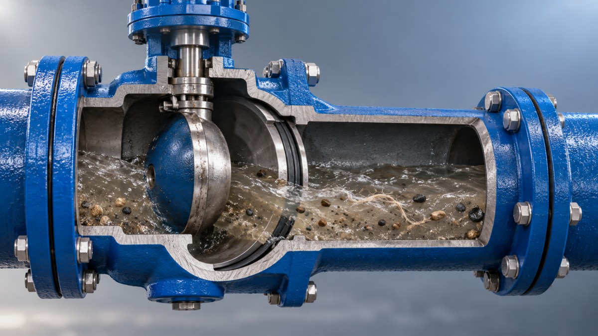
At full opening, the hemispherical element rotates away from much of the main flow stream. Whether the resulting passage is effectively full bore or remains restricted must be checked against the drawing. Nominal size is not the minimum free-passage dimension. Shaft projections, seat retainers, and body pockets can still provide snagging points or collection zones.
Grit, fibers, and sludge create different failure modes
A wastewater solids concentration alone is insufficient for selection. Fine mineral particles, long textile fibers, and cohesive sludge may occur in the same line, yet each challenges the valve differently.
Consider both normal operation and shutdown conditions. A line that carries grit successfully at pumping velocity may accumulate a bed of solids when the pump stops. The next closure can then require substantially different torque from a clean-water factory test. Increasing actuator output without investigating the obstruction may damage the seat, shaft, or gearbox.
Materials: separate pressure containment from wear resistance
A ductile iron body can provide pressure containment in a ductile iron pipeline, but the body material alone does not establish wastewater compatibility. Review the complete wetted assembly: lining, closure surface, seat, shaft, fasteners, and seals. Temperature, pH, chlorides, sulfides, and intermittent cleaning chemicals can affect these components differently.
Resilient seats can provide tight shutoff, but sharp particles may cut them and trapped grit may cause indentation. Metal seats may tolerate some abrasive duties better, depending on alloy and surface treatment, but their specified leakage performance may differ. Neither “soft seated” nor “metal seated” is enough information to approve the valve.
Request the actual seat material, mating-surface specification, replaceability, and chemical compatibility limits. For coated bodies, inspect how coating continuity is maintained around seat pockets and machined interfaces. A hard sealing surface does not protect adjacent uncoated areas from corrosion, and coating damage can create rough surfaces that retain deposits.
Operating conditions that can defeat a suitable design
Prolonged operation near the closed position
A small opening concentrates velocity and particle impact near the sealing region. Even when full-open flow is acceptable, continuous throttling may accelerate erosion or create vibration. Obtain the manufacturer’s allowable control range and assess cavitation where pressure drops are significant. An isolation-duty valve should not automatically be assigned continuous flow-control duty.
Pressure direction and actuator torque
Some eccentric arrangements have a preferred pressure direction for sealing or operation. Reverse pressure can change both seat loading and required torque. Confirm the required shutoff direction, maximum differential pressure, and whether reverse-flow conditions occur during pump trips or network changes.
Actuator selection should account for seating, unseating, running torque, packing friction, and the specified service margin. Also verify torque limits for the valve and gearbox. The objective is adequate operating capacity without making destructive force available during a jam.
Installation orientation and closure timing
Do not assume every shaft orientation is equally suitable for settling solids. Follow the manufacturer’s installation instructions and examine where sediment will collect relative to the seat and closure sweep. Check the closure time against system surge requirements; changing the final portion of travel can affect hydraulic transients. Maintenance work requires isolation, depressurization, and appropriate wastewater exposure controls.
Evidence to request before approving the valve
Technical approval should connect the offered construction to defined service conditions. A useful submittal includes:
- Sectional and dimensional drawings: minimum free passage, closure sweep, seat location, flange dimensions, and maintenance clearances.
- A duty-specific torque assessment: differential pressure, pressure direction, actuator supply conditions, and permissible shaft torque.
- Material details: wetted grades, elastomer identification, coating system, and relevant chemical limitations.
- A defined leakage test: test medium, pressure, duration, direction, and acceptance criterion.
- Maintenance instructions: inspection access, seat replacement method, spare parts, and required removal space.
Where ISO 5208 or EN 12266-1 is specified, identify the applicable edition, test requirements, and leakage acceptance rather than accepting a general statement of compliance. These pressure-testing standards do not establish resistance to ragging or abrasive wastewater. Flange compatibility and pressure-temperature ratings also require separate confirmation against the project specification.
Clean-water leakage results establish performance under the stated test conditions, not guaranteed shutoff after prolonged exposure to grit. Where debris handling is critical, request relevant documented service evidence or an agreed representative test. Define the solids and operating sequence beforehand so the evidence addresses the intended duty.
Diagnosing leakage after commissioning
When a valve stops sealing, first distinguish incomplete travel from damaged sealing surfaces. Compare actual shaft position with the position indicator, then check actuator limits, torque-trip records, and differential pressure. An indicator showing “closed” does not necessarily prove that the closure has reached its correct seating position.
If the operating instructions permit it, a controlled reopening and flushing sequence may clear loose deposits. Repeatedly forcing closure against a persistent obstruction is not a repair. Leakage that continues after verified travel and cleaning warrants inspection for embedded grit, seat cuts, erosion, or misalignment.
Plan physical access as part of that inspection strategy. A ductile iron chamber-access item such as Ductile Iron Manhole Cover9 is separate from the valve’s hydraulic performance; its suitability for a particular chamber requires its own dimensional and loading assessment. The chamber must also provide sufficient clearance to operate, inspect, and remove valve components safely.
Persistent recurring blockage points back to the application: inadequate screening, unfavorable orientation, sediment accumulation, or insufficient free passage. Resolving those conditions is more effective than repeatedly increasing closing torque or replacing the same damaged seat.
Navigation
Send Us A Message

First class quality service and professional after-sales team.
Get in Touch
*We respect your confidentiality and all information are protected.