Ductile Iron Pipe for Sewage Force Mains: Planning for Surge Pressure
A sewage pumping station loses power. Flow slows, the check valve closes, and a pressure wave travels along the force main. Depending on the pipeline profile and pump behavior, the first concern may be a pressure drop rather than a pressure spike. When separated liquid columns rejoin, the resulting pressure rise can exceed normal operating conditions.
For project managers specifying Ductile Iron Pipe for Sewage force mains, surge planning therefore means more than choosing a stronger pipe. Pipe walls, joints, fittings, valves, restraints, and protective devices must work as one system. Resolving those interfaces during design is considerably easier than discovering a mismatch after materials arrive on site.
Start with the pressure envelope, not the operating pressure
A force main does not have one governing pressure. Normal duty, pump shutoff, transient events, and field testing each create different demands. The design team needs a pressure envelope showing the maximum and minimum pressures along the entire route, not simply a discharge-pressure reading at the station.
Ask the hydraulic designer to evaluate scenarios that reflect how the station will actually operate:
- Loss of power with one or several pumps running.
- Pump startup, controlled shutdown, and changes in duty combinations.
- Check-valve closure, including possible reverse flow before closure.
- Isolation-valve operation under credible flow conditions.
- Air accumulation, air release, and pipeline filling or draining.
- Future flow rates and planned station expansion.
The route profile matters as much as the equipment list. High points can experience low pressure and collect gas; lower elevations may experience higher static pressure. A pipe class selected from average conditions can miss both problems.
Use a screening calculation carefully
The Joukowsky relationship, ΔP = ρaΔV, gives a useful first estimate of pressure change from a rapid velocity change. Here, ρ is fluid density, a is pressure-wave speed, and ΔV is the velocity change. It helps explain why a modest change in flow velocity can produce a substantial pressure event.
It is not a substitute for transient modeling on a complex sewage force main. Wave reflections, pump inertia, valve behavior, entrained gas, and column separation can change the result significantly. Wave speed also depends on the pipe and fluid system; a generic value should not become an unexamined design assumption.
Turn the transient study into procurement requirements
A surge report becomes useful to procurement only when its findings become clear acceptance criteria. Require the designer to identify maximum transient pressure, minimum pressure, event duration, and expected repetition where fatigue assessment is relevant. Results should identify critical locations and component requirements, not merely present a graph at the pumping station.
The following distinctions help prevent common specification gaps:
Do not add a generic surge allowance to every catalog pressure rating. Some rating systems already define separate operating, maximum allowable, and test pressures. The engineer must confirm how the selected standard treats each condition and whether the complete assembly satisfies it.
What K9 does—and does not—tell you
A designation such as K9 describes a wall-thickness class within the applicable dimensional system; it is not, by itself, a universal pressure rating. Diameter, material requirements, joint design, fittings, and the governing standard all affect suitability. Buried-pipe design must also account for cover, traffic loads, bedding, and soil support.
For example, Shanxi Datong Foundry Co.,Ltd. offers Ductile Iron Pipe K9 within a stated DN80–DN2600 range, with push-on, flanged, and self-restrained joint options. Its published working-pressure range of 1.0–1.6 MPa is a starting point for inquiry, not evidence that every diameter and joint combination meets a particular force-main surge envelope.
Request confirmation for the actual schedule: diameter, wall thickness, lining, joint type, fitting arrangement, and required pressure conditions. For sewage service, establish the applicable wastewater requirements, such as EN 598 where specified. Water-supply standards or drinking-water approvals alone do not establish suitability for wastewater exposure.
The company manufactures ductile iron pipes, fittings, and rubber sealing rings through integrated smelting and casting operations. That scope provides an opportunity to coordinate component interfaces, but the project still needs documented compatibility and pressure limits for the supplied assembly.
Keep the pipe connected when pressure changes direction
A pipe barrel can withstand internal pressure while a poorly restrained connection still moves or separates. Unbalanced thrust occurs at bends, tees, reducers, dead ends, and closed valves. Transients can increase these forces or change the loading pattern.
Standard push-on joints generally provide sealing and flexibility, not axial restraint unless specifically designed and rated for it. Where restraint is needed, identify the approved restrained-joint system and required restrained lengths. Alternatively, engineer thrust blocks using verified soil conditions, bearing capacity, and available space.
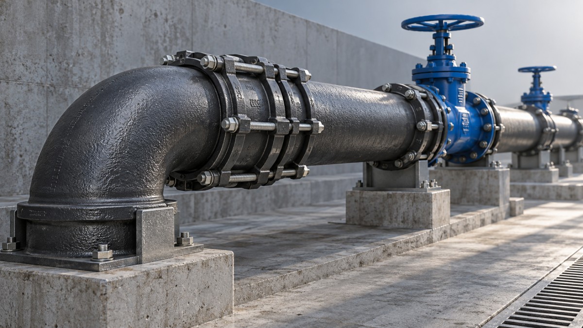
A coordinated layout should show restraints alongside bends, valves, changes in diameter, and surge-control equipment. This makes interfaces visible before excavation. Pay particular attention to station connections, chambers, and transitions between pipe materials, where stiffness and movement allowances differ.
Flanged joints also need careful review. Flange ratings, bolts, gaskets, alignment, and support must match the design conditions. Treating a flange as automatically stronger than every other connection can hide the weakest component in the pressure boundary.
Choose surge protection that can survive sewage service
The objective is not simply to suppress the highest pressure peak. A protection strategy should control excessive positive pressure while limiting damaging low-pressure conditions. Its performance must be checked in the transient model.
- Pump controls: Variable-speed ramps or controlled shutdown may moderate routine transients, but cannot be assumed effective during total power loss without suitable backup provisions.
- Check valves: Select closure characteristics to suit system deceleration. “Slow closing” is not automatically safer; excessive reverse flow before closure can worsen slam.
- Surge vessels or other protective devices: Evaluate sizing, connection losses, operating settings, and maintenance access together.
- Air-management valves: Use wastewater-suitable designs and assess both air admission and release. Rapid air expulsion can itself create a pressure event.
Sewage brings solids, grease, gas, and fouling. A protective device that performs well when clean may behave differently after service exposure. Isolation arrangements, cleaning access, safe venting, and an achievable inspection schedule belong in the design—not in a later maintenance discussion.
Close the gaps before construction and commissioning
Surge resistance does not replace corrosion protection. Confirm that internal lining suits the wastewater chemistry and possible hydrogen sulfide exposure, while external protection addresses soil conditions and stray-current risks. Elastomer selection should also reflect the conveyed fluid and temperature.
Before releasing the pipe order, hold a focused review involving the hydraulic designer, pump and valve suppliers, pipe manufacturer, contractor, and operator. Close out three questions: Does every component meet the pressure envelope? Is every thrust location addressed? Can the operator maintain the protective equipment?
Commissioning should then verify valve settings, pump sequences, air-management arrangements, and instrumentation against the design. Any transient testing should follow an engineered procedure rather than deliberately creating an uncontrolled trip.
Reliable Ductile Iron Pipe for Sewage force mains depend on those connections between analysis, purchasing, installation, and operation. A clear pressure envelope and a coordinated component schedule give project managers something more useful than a broad assurance of strength: a defensible basis for accepting the system.
Navigation
Send Us A Message

First class quality service and professional after-sales team.
Get in Touch
*We respect your confidentiality and all information are protected.